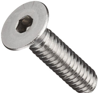
Countersunk Flat Head Screws & Flat Head Machine Screws: Manufacturer & Exporter
A flat head screw sinks into a cone-shaped countersink and finishes flush with the surface. Nothing stands proud to snag, and the cone centres the part on the screw.
Exotic Alloy manufactures flat head screws in Mumbai, India, for electronics, enclosure, machinery, hardware and furniture makers. We stock across India and export to Japan, South-East Asia, the Gulf, Europe and the Americas. Heads are cold formed with the slot or recess, and threads are rolled.
Two angles, one idea
Inch flat heads to ASME B18.6.3 have an 82° head; metric countersunk screws to ISO 2009 (slotted, formerly DIN 963) and ISO 7046 (cross recessed, formerly DIN 965) have a 90° head. Hex socket flat heads like the one in our photo are covered on our countersunk bolts page; for a raised top see oval head screws.
- Head
- Countersunk cone with a flat top
- Angle
- 82° inch (ASME); 90° metric (ISO)
- Length
- Overall, head included
- Drives
- Slot, Phillips, Pozidriv, hexalobular, hex socket
- Sheet
- At least as thick as the head
- Related
- Countersunk screws, oval head, countersunk bolts
Flat Head Screw Specification
The range we manufacture and supply.
82° or 90°? Matching Head and Countersink
The most common flat head mistake is an inch screw in a metric countersink, or the other way round.
| Screw | Head angle | Countersink tool | Typical standards |
|---|---|---|---|
| Inch machine screw | 82° | 82° | ASME B18.6.3, ASME B18.3 (socket) |
| Metric screw | 90° | 90° | ISO 2009, ISO 7046, ISO 14581, ISO 10642 |
| Thin-sheet inch screw | 100° | 100° | ASME B18.6.3 100° heads (to order) |
Flat Head Screw Dimensions
| Size | P | dk theor. max | dk actual max / min | k max | n slot nom (ISO 2009) | t slot min (ISO 2009) | Recess ISO 7046-1 | m ≈ H / Z |
|---|---|---|---|---|---|---|---|---|
| M1.6 | 0.35 | 3.6 | 3 / 2.7 | 1 | 0.4 | 0.32 | 0 | 1.6 / 1.6 |
| M2 | 0.4 | 4.4 | 3.8 / 3.5 | 1.2 | 0.5 | 0.4 | 0 | 1.9 / 1.9 |
| M2.5 | 0.45 | 5.5 | 4.7 / 4.4 | 1.5 | 0.6 | 0.5 | 1 | 2.9 / 2.8 |
| M3 | 0.5 | 6.3 | 5.5 / 5.2 | 1.65 | 0.8 | 0.6 | 1 | 3.2 / 3 |
| M3.5 | 0.6 | 8.2 | 7.3 / 6.94 | 2.35 | 1 | 0.9 | 2 | 4.4 / 4.1 |
| M4 | 0.7 | 9.4 | 8.4 / 8.04 | 2.7 | 1.2 | 1 | 2 | 4.6 / 4.4 |
| M5 | 0.8 | 10.4 | 9.3 / 8.94 | 2.7 | 1.2 | 1.1 | 2 | 5.2 / 4.9 |
| M6 | 1 | 12.6 | 11.3 / 10.87 | 3.3 | 1.6 | 1.2 | 3 | 6.8 / 6.6 |
| M8 | 1.25 | 17.3 | 15.8 / 15.37 | 4.65 | 2 | 1.8 | 4 | 8.9 / 8.8 |
| M10 | 1.5 | 20 | 18.3 / 17.78 | 5 | 2.5 | 2 | 4 | 10 / 9.8 |
ISO 2009 (slotted) and ISO 7046-1 (cross recessed) countersunk flat head screws, product grade A, mm. H = Phillips, Z = Pozidriv.
| Size | A head dia. max / min | H head height max / min | J slot width max / min | T slot depth max / min | Threads UNC / UNF |
|---|---|---|---|---|---|
| No. 0 | .112 / .096 | .035 / .026 | .023 / .016 | .015 / .010 | 80 (UNF) |
| No. 1 | .137 / .120 | .043 / .033 | .026 / .019 | .019 / .012 | 64 / 72 |
| No. 2 | .162 / .144 | .051 / .040 | .031 / .023 | .023 / .015 | 56 / 64 |
| No. 3 | .187 / .167 | .059 / .047 | .035 / .027 | .027 / .017 | 48 / 56 |
| No. 4 | .212 / .191 | .067 / .055 | .039 / .031 | .030 / .020 | 40 / 48 |
| No. 5 | .237 / .215 | .075 / .062 | .043 / .035 | .034 / .022 | 40 / 44 |
| No. 6 | .262 / .238 | .083 / .069 | .048 / .039 | .038 / .024 | 32 / 40 |
| No. 8 | .312 / .285 | .100 / .084 | .054 / .045 | .045 / .029 | 32 / 36 |
| No. 10 | .362 / .333 | .116 / .098 | .060 / .050 | .053 / .034 | 24 / 32 |
| No. 12 | .412 / .380 | .132 / .112 | .067 / .056 | .060 / .039 | 24 / 28 |
| 1/4″ | .477 / .442 | .153 / .131 | .075 / .064 | .070 / .046 | 20 / 28 |
| 5/16″ | .597 / .556 | .191 / .165 | .084 / .072 | .088 / .058 | 18 / 24 |
| 3/8″ | .717 / .670 | .230 / .200 | .094 / .081 | .106 / .070 | 16 / 24 |
| 1/2″ | .815 / .765 | .223 / .186 | .106 / .091 | .103 / .065 | 13 / 20 |
ASME B18.6.3 82° flat heads for machine screws, slotted, inches. A max is the theoretical sharp-edged diameter.
| Size | M recess dia. ref | R recess depth ref | N recess width ref | Phillips driver | G gaging dia. | F protrusion max / min |
|---|---|---|---|---|---|---|
| No. 0 | .062 | .035 | .014 | PH 0 | .078 | .026 / .016 |
| No. 1 | .070 | .043 | .015 | PH 0 | .101 | .028 / .016 |
| No. 2 | .096 | .055 | .017 | PH 1 | .124 | .029 / .017 |
| No. 3 | .100 | .060 | .018 | PH 1 | .148 | .031 / .018 |
| No. 4 | .122 | .081 | .018 | PH 1 | .172 | .032 / .019 |
| No. 5 | .148 | .074 | .027 | PH 2 | .196 | .034 / .020 |
| No. 6 | .168 | .094 | .029 | PH 2 | .220 | .036 / .021 |
| No. 8 | .182 | .110 | .030 | PH 2 | .267 | .039 / .023 |
| No. 10 | .198 | .124 | .032 | PH 2 | .313 | .042 / .025 |
| No. 12 | .262 | .144 | .035 | PH 3 | .362 | .045 / .027 |
| 1/4″ | .276 | .160 | .036 | PH 3 | .424 | .050 / .029 |
| 5/16″ | .358 | .205 | .061 | PH 4 | .539 | .057 / .034 |
| 3/8″ | .386 | .234 | .065 | PH 4 | .653 | .065 / .039 |
| 1/2″ | .418 | .265 | .069 | PH 4 | .739 | .081 / .049 |
ASME B18.6.3 Phillips recess (reference) and protrusion gauging, inches: with the countersink at the gaging diameter G, the head top stands F above the surface.
Countersinks & Sheet Thickness for Flat Head Screws
| Size | Countersink Ø flush top, 90° | Depth = min. sheet k | Clearance hole ISO 273 medium |
|---|---|---|---|
| M1.6 | 3.6 | 1 | 1.8 |
| M2 | 4.4 | 1.2 | 2.4 |
| M2.5 | 5.5 | 1.5 | 2.9 |
| M3 | 6.3 | 1.65 | 3.4 |
| M3.5 | 8.2 | 2.35 | 3.9 |
| M4 | 9.4 | 2.7 | 4.5 |
| M5 | 10.4 | 2.7 | 5.5 |
| M6 | 12.6 | 3.3 | 6.6 |
| M8 | 17.3 | 4.65 | 9 |
| M10 | 20 | 5 | 11 |
Our calculation from the ISO head: cut to the theoretical diameter, the flat top sits flush and a narrow ring of countersink shows round the slightly smaller real edge.
The material must be at least as thick as the head. In thinner sheet the countersink cuts right through, the hole edge becomes a knife edge, and the head can pull through or work loose.
| Size | Flat head ISO 2009 slot depth t min | Raised head ISO 2010 slot depth t min |
|---|---|---|
| M1.6 | 0.32 | 0.65 |
| M2 | 0.4 | 0.8 |
| M2.5 | 0.5 | 1 |
| M3 | 0.6 | 1.2 |
| M3.5 | 0.9 | 1.4 |
| M4 | 1 | 1.6 |
| M5 | 1.1 | 2 |
| M6 | 1.2 | 2.4 |
| M8 | 1.8 | 3.2 |
| M10 | 2 | 3.8 |
A flat head has room for only a shallow slot; the raised (oval) head of ISO 2010 allows a deeper one (mm).
Threads & Tap Drills for Flat Head Machine Screws
UNC and UNF threads for every inch size, with the drill for about 75 % thread. No. 0 is made in UNF only.
| Size | Thread | Tap drill 75 % thread | Thread | Tap drill 75 % thread |
|---|---|---|---|---|
| No. 0 | – | – | #0-80 | 3/64″ (0.0469″) |
| No. 1 | #1-64 | #53 (0.0595″) | #1-72 | #53 (0.0595″) |
| No. 2 | #2-56 | #50 (0.0700″) | #2-64 | #50 (0.0700″) |
| No. 3 | #3-48 | #47 (0.0785″) | #3-56 | #45 (0.0820″) |
| No. 4 | #4-40 | #43 (0.0890″) | #4-48 | #42 (0.0935″) |
| No. 5 | #5-40 | #38 (0.1015″) | #5-44 | #37 (0.1040″) |
| No. 6 | #6-32 | #36 (0.1065″) | #6-40 | #33 (0.1130″) |
| No. 8 | #8-32 | #29 (0.1360″) | #8-36 | #29 (0.1360″) |
| No. 10 | #10-24 | #25 (0.1495″) | #10-32 | #21 (0.1590″) |
| No. 12 | #12-24 | #16 (0.1770″) | #12-28 | #14 (0.1820″) |
| 1/4″ | 1/4-20 | #7 (0.2010″) | 1/4-28 | #3 (0.2130″) |
| 5/16″ | 5/16-18 | F (0.2570″) | 5/16-24 | I (0.2720″) |
| 3/8″ | 3/8-16 | 5/16″ (0.3125″) | 3/8-24 | Q (0.3320″) |
| 1/2″ | 1/2-13 | 27/64″ (0.4219″) | 1/2-20 | 29/64″ (0.4531″) |
Number, letter and fractional drills with their diameters in inches.
Flat Head Flush-Fit Calculator
Enter the countersink diameter and the sheet thickness. See where the head top will sit, how deep the countersink goes and whether the sheet is thick enough.
Screw & countersink
Our calculation. Metric: head top = (theoretical head diameter − countersink diameter) ÷ 2 for a 90° countersink. Inch: from the ASME gauge values, F − (countersink − G) ÷ (2 tan 41°). The countersink resets to the flush value when you change size.
Result
Flat Head Screw Materials & Grades
| Material | Class | Finish | Best for |
|---|---|---|---|
| A2 stainless (304) | A2-70 | Plain, passivated | Electronics, enclosures, general use |
| A4 stainless (316) | A4-70 | Plain, passivated | Marine, food and chemical equipment |
| Carbon steel | 4.8 (ISO 7046-1), 8.8 (ISO 7046-2) | Zinc plated, black | Machinery and dry assemblies |
| Brass | – | Plain, nickel | Electrical and decorative parts |
How Our Flat Head Screws Are Made
Wire
Stainless, steel or brass wire, certified by heat or lot.
Cold heading
Cone and recess formed together at 82° or 90°; slots punched or sawn.
Thread rolling
UNC / UNF or metric threads rolled to the head.
Heat treatment
For 8.8 steel; stainless and 4.8 as formed.
Finishing
Passivation, zinc, black oxide or nickel.
Inspection
Head angle, diameter, flushness and recess checked.
Where Our Flat Head Screws Are Used
Electronics
Flush covers, chassis and heat sinks.
Enclosures & racks
Panels and rails that must slide past each other.
Hinges & hardware
Hinge leaves that close flat over the screw heads.
Machinery
Guides, wear strips and slides with nothing standing proud.
Marine fittings
A4 flat heads on deck plates and trim.
Furniture
Knock-down fittings with flush heads.
Flat Head Screw Inspection & Certification
| Check | Method | Applied to |
|---|---|---|
| Head angle & flushness | Protrusion gauge (F at G) / countersink gauge | Every lot |
| Head diameter | Micrometer: A / dk | Every lot |
| Slot / recess | Slot gauges; recess penetration gauge | Every lot |
| Thread | GO / NO-GO ring gauges | Every lot |
| Length | Overall, head included | Every lot |
| Material | PMI / chemical analysis | Stainless and brass lots |
Every shipment includes
- Mill certificate with heat number
- Dimensional report
- Lot number on every box
On request
- EN 10204 3.1 certificate
- Salt spray test for plated lots
- Count-checked kits and labels