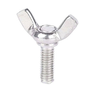
DIN 316 & ASME Wing Screws (Butterfly Screws): Manufacturer & Stockist
A butterfly screw has two flat wings instead of a drive. Finger and thumb turn it, so covers, guards, clamps and fixtures can be opened and closed again and again without looking for a tool.
Exotic Alloy manufactures butterfly screws in Mumbai, India, and keeps common sizes in stock for machine builders, furniture and display makers, and maintenance teams. We supply across India and export to Tanzania, East Africa, the Gulf and Europe.
Made for hand tightening
The wings give a long lever for the fingers, but they are not meant for spanners or pliers. Where a joint needs real preload, use a hex cap screw; for a smaller knob see knurled head screws and thumb screws.
- Also called
- Wing screw, wing bolt, thumb wing screw
- Metric
- DIN 316 rounded, DIN 318 edged
- Inch
- ASME B18.6.8 Types A–D
- Length
- From the bearing face
- Tightened
- By hand only
- Related
- Wing nuts, knurled, thumb screws
Butterfly Screw Specification
The range we manufacture and supply.
Rounded, Edged & ASME Type A to D Wings
Two metric wing shapes and six inch types and styles.
| Type | Make | Sizes | Spread A, 1/4 in size max, in | Height B, 1/4 in size max, in | Wing thickness C 1/4 in size, max |
|---|---|---|---|---|---|
| Type A | cold forged, light / regular / heavy wings | No. 4 to 5/8 | 1.25 (regular) | .66 | .21 |
| Type B, style 1 | round nose, steel (UNS G10060) | No. 10 to 5/8 | 1.16 | .56 | .17 |
| Type B, style 2 | high head and round nose | No. 10 to 3/8 | 1.22 | .94 | .16 |
| Type C, style 1 | die cast, zinc alloy (UNS Z33520) | No. 6 to 3/8 | 1.08 | .56 | .17 |
| Type C, style 2 | zinc alloy (UNS Z33520) or steel (UNS G10060) | No. 6 to 1/2 | 1.08 | .57 | .16 |
| Type D | stamped from steel sheet (UNS G10060) | No. 6 to 3/8 | 1.09 | .46 | .26 |
ASME B18.6.8-2010. Make and material from the standard’s table titles; values in inches.
Wing Screw Dimensions
| Size | Wing span e max / min | Head height h max / min | Boss d2 bearing, max / min | Boss d3 top, max / min | Boss height m max / min | Wing g / G tip / root, min | a max under head |
|---|---|---|---|---|---|---|---|
| M4 × 0.7 | 20 / 18 | 10.5 / 8.5 | 8 / 6 | 7 / 5.5 | 4.6 / 3.2 | 1.1 / 1.7 | 2.1 |
| M5 × 0.8 | 26 / 24 | 13 / 11 | 11 / 8 | 9 / 7.5 | 6.5 / 4 | 1.5 / 2.3 | 2.4 |
| M6 × 1 | 33 / 30 | 17 / 15 | 13 / 10 | 11 / 9 | 8 / 5 | 1.5 / 2.7 | 3 |
| M8 × 1.25 | 39 / 36 | 20 / 18 | 16 / 13 | 12.5 / 10.5 | 10 / 6.5 | 2 / 3.6 | 4 |
| M10 × 1.5 | 51 / 48 | 25 / 23 | 20 / 17 | 16.5 / 14.5 | 12 / 8 | 3.6 / 4.6 | 4.5 |
| M12 × 1.75 | 65 / 62 | 33.5 / 31 | 23 / 20 | 19.5 / 17.5 | 14 / 10 | 4.1 / 5.6 | 5.3 |
| M16 × 2 | 73 / 70 | 37.5 / 35 | 29 / 26 | 23 / 21 | 17 / 13 | 5.6 / 6.5 | 6 |
| M20 × 2.5 | 90 / 86 | 46.5 / 44 | 35 / 32 | 29 / 27 | 21 / 16 | 6.1 / 7 | 7.5 |
| M24 × 3 | 110 / 106 | 56.5 / 53.5 | 44 / 41 | 37.5 / 35 | 25 / 20 | 8.6 / 9.5 | 9 |
DIN 316, mm (1983, 1998 and 2016 editions give the same values). Bold: the M12 head height max is 33.5 here and 35.5 in the DIN 315 wing nut.
| Length l | M4 | M5 | M6 | M8 | M10 | M12 | M16 | M20 | M24 |
|---|---|---|---|---|---|---|---|---|---|
| 6 | |||||||||
| 8 | |||||||||
| 10 | |||||||||
| 12 | |||||||||
| 14 | |||||||||
| 16 | |||||||||
| 18 | |||||||||
| 20 | |||||||||
| 25 | |||||||||
| 30 | |||||||||
| 35 | |||||||||
| 40 | |||||||||
| 45 | |||||||||
| 50 | |||||||||
| 60 |
DIN 316 commercial lengths, mm, measured from the bearing face. Other lengths to order.
| Size | Wing span n, max / min | Head height H, max / min | Boss dk, max / min | Boss height k, max / min | DIN 316 span for comparison |
|---|---|---|---|---|---|
| M4 | 21 / 19 | 11 / 9 | 9 / 7 | 4.6 / 3.2 | 20 / 18 |
| M5 | 26.5 / 24.5 | 13 / 11 | 12 / 9 | 6 / 4 | 26 / 24 |
| M6 | 32 / 29 | 16 / 14 | 14 / 11 | 7 / 5 | 33 / 30 |
| M8 | 38 / 35 | 19 / 17 | 16 / 13 | 8.5 / 6.5 | 39 / 36 |
| M10 | 50 / 47 | 24 / 22 | 21 / 18 | 10 / 8 | 51 / 48 |
| M12 | 66 / 63 | 32 / 29 | 24 / 21 | 13 / 10 | 65 / 62 |
DIN 318 (1999 / 2016), mm.
| Size & series | Threads per inch | Spread A max / min | Height B max / min | Wing thickness C max / min | Boss dia. max / min | Boss height max / min | Lengths min–max |
|---|---|---|---|---|---|---|---|
| No. 4 Heavy | 40 | .72 / .59 | .41 / .28 | .11 / .07 | .33 / .29 | .14 / .10 | .25–.75 |
| No. 6 Light | 32 | .72 / .59 | .41 / .28 | .11 / .07 | .33 / .29 | .14 / .10 | .25–.75 |
| No. 6 Heavy | 32 | .91 / .78 | .47 / .34 | .14 / .10 | .43 / .39 | .18 / .14 | .25–.75 |
| No. 8 Light | 32 | .91 / .78 | .47 / .34 | .14 / .10 | .43 / .39 | .18 / .14 | .38–.75 |
| No. 8 Heavy | 32 | 1.10 / .97 | .57 / .43 | .18 / .14 | .50 / .45 | .22 / .17 | .38–.75 |
| No. 10 Light | 24, 32 | .91 / .78 | .47 / .34 | .14 / .10 | .43 / .39 | .18 / .14 | .38–1.00 |
| No. 10 Heavy | 24, 32 | 1.10 / .97 | .57 / .43 | .18 / .14 | .50 / .45 | .22 / .17 | .38–1.00 |
| No. 12 Light | 24 | 1.10 / .97 | .57 / .43 | .18 / .14 | .50 / .45 | .22 / .17 | .38–1.00 |
| No. 12 Heavy | 24 | 1.25 / 1.12 | .66 / .53 | .21 / .17 | .58 / .51 | .25 / .20 | .38–1.50 |
| 1/4 Light | 20 | 1.10 / .97 | .57 / .43 | .18 / .14 | .50 / .45 | .22 / .17 | .50–1.50 |
| 1/4 Regular | 20 | 1.25 / 1.12 | .66 / .53 | .21 / .17 | .58 / .51 | .25 / .20 | .50–1.50 |
| 1/4 Heavy | 20 | 1.44 / 1.31 | .79 / .65 | .24 / .20 | .70 / .64 | .30 / .26 | .50–1.50 |
| 5/16 Light | 18 | 1.25 / 1.12 | .66 / .53 | .21 / .17 | .58 / .51 | .25 / .20 | .50–1.50 |
| 5/16 Regular | 18 | 1.44 / 1.31 | .79 / .65 | .24 / .20 | .70 / .64 | .30 / .26 | .50–1.50 |
| 5/16 Heavy | 18 | 1.94 / 1.81 | 1.00 / .87 | .33 / .26 | .93 / .86 | .39 / .35 | .50–1.50 |
| 3/8 Light | 16 | 1.44 / 1.31 | .79 / .65 | .24 / .20 | .70 / .64 | .30 / .26 | .75–2.00 |
| 3/8 Regular | 16 | 1.94 / 1.81 | 1.00 / .87 | .33 / .26 | .93 / .86 | .39 / .35 | .75–2.00 |
| 3/8 Heavy | 16 | 2.76 / 2.62 | 1.44 / 1.31 | .40 / .34 | 1.19 / 1.13 | .55 / .51 | .75–2.00 |
| 7/16 Light | 14 | 1.94 / 1.81 | 1.00 / .87 | .33 / .26 | .93 / .86 | .39 / .35 | 1.00–4.00 |
| 7/16 Heavy | 14 | 2.76 / 2.62 | 1.44 / 1.31 | .40 / .34 | 1.19 / 1.13 | .55 / .51 | 1.00–4.00 |
| 1/2 Light | 13 | 1.94 / 1.81 | 1.00 / .87 | .33 / .26 | .93 / .86 | .39 / .35 | 1.00–4.00 |
| 1/2 Heavy | 13 | 2.76 / 2.62 | 1.44 / 1.31 | .40 / .34 | 1.19 / 1.13 | .55 / .51 | 1.00–4.00 |
| 5/8 Heavy | 11 | 2.76 / 2.62 | 1.44 / 1.31 | .40 / .34 | 1.19 / 1.13 | .55 / .51 | 1.25–4.00 |
ASME B18.6.8-2010 Type A, inch (same as B18.17-1968 except the No. 12 Heavy length range, now up to 1.50 in).
| Type | Size | Threads per inch | Spread A max / min | Height B max / min | Wing thickness C max / min | Lengths min–max |
|---|---|---|---|---|---|---|
| Type B, style 1 | No. 10 | 24 | .97 / .91 | .45 / .39 | .15 / .12 | .50–2.00 |
| Type B, style 1 | 1/4 | 20 | 1.16 / 1.09 | .56 / .50 | .17 / .14 | .50–3.00 |
| Type B, style 1 | 5/16 | 18 | 1.44 / 1.38 | .67 / .61 | .18 / .15 | .50–3.00 |
| Type B, style 1 | 3/8 | 16 | 1.72 / 1.66 | .80 / .73 | .20 / .17 | .50–4.00 |
| Type B, style 1 | 7/16 | 14 | 2.00 / 1.94 | .91 / .84 | .21 / .18 | 1.00–3.00 |
| Type B, style 1 | 1/2 | 13 | 2.31 / 2.22 | 1.06 / .94 | .23 / .20 | 1.00–3.00 |
| Type B, style 1 | 5/8 | 11 | 2.84 / 2.72 | 1.31 / 1.19 | .27 / .23 | 1.00–2.50 |
| Type B, style 2 | No. 10 | 24 | 1.01 / .95 | .78 / .72 | .14 / .11 | .50–1.25 |
| Type B, style 2 | 1/4 | 20 | 1.22 / 1.16 | .94 / .88 | .16 / .13 | .50–2.00 |
| Type B, style 2 | 5/16 | 18 | 1.43 / 1.37 | 1.09 / 1.03 | .17 / .14 | .50–2.00 |
| Type B, style 2 | 3/8 | 16 | 1.63 / 1.57 | 1.25 / 1.19 | .18 / .15 | .50–2.00 |
| Type C, style 1 | No. 6 | 32 | .85 / .83 | .45 / .43 | .15 / .12 | .25–.75 |
| Type C, style 1 | No. 8 | 32 | .85 / .83 | .45 / .43 | .15 / .12 | .38–1.00 |
| Type C, style 1 | No. 10 | 24, 32 | .85 / .83 | .45 / .43 | .15 / .12 | .38–1.25 |
| Type C, style 1 | 1/4 | 20 | 1.08 / 1.05 | .56 / .53 | .17 / .14 | .50–1.50 |
| Type C, style 1 | 5/16 | 18 | 1.23 / 1.20 | .64 / .62 | .22 / .19 | .50–1.50 |
| Type C, style 1 | 3/8 | 16 | 1.45 / 1.42 | .74 / .72 | .24 / .21 | .50–1.50 |
| Type C, style 2 | No. 6 | 32 | .85 / .83 | .43 / .42 | .14 / .12 | .25–1.00 |
| Type C, style 2 | No. 8 | 32 | .85 / .83 | .43 / .42 | .14 / .12 | .38–1.00 |
| Type C, style 2 | No. 10 | 24, 32 | .85 / .83 | .43 / .42 | .14 / .12 | .38–2.00 |
| Type C, style 2 | 1/4 | 20 | 1.08 / 1.05 | .57 / .53 | .16 / .14 | .50–2.50 |
| Type C, style 2 | 5/16 | 18 | 1.23 / 1.20 | .64 / .62 | .20 / .18 | .50–3.00 |
| Type C, style 2 | 3/8 | 16 | 1.45 / 1.42 | .74 / .72 | .23 / .21 | .75–3.00 |
| Type C, style 2 | 7/16 | 14 | 1.89 / 1.86 | .91 / .90 | .29 / .28 | 1.00–4.00 |
| Type C, style 2 | 1/2 | 13 | 1.89 / 1.86 | .91 / .90 | .29 / .28 | 1.00–4.00 |
| Type D | No. 6 | 32 | .78 / .72 | .40 / .34 | .18 / .12 | .25–.75 |
| Type D | No. 8 | 32 | .78 / .72 | .40 / .34 | .18 / .12 | .38–.75 |
| Type D | No. 10 | 24 | .90 / .84 | .46 / .40 | .21 / .15 | .38–1.00 |
| Type D | No. 12 | 24 | 1.09 / 1.03 | .46 / .40 | .26 / .20 | .38–1.00 |
| Type D | 1/4 | 20 | 1.09 / 1.03 | .46 / .40 | .26 / .20 | .50–1.50 |
| Type D | 5/16 | 18 | 1.31 / 1.25 | .62 / .56 | .29 / .23 | .50–1.50 |
| Type D | 3/8 | 16 | 1.31 / 1.25 | .62 / .56 | .29 / .23 | .75–2.00 |
ASME B18.6.8-2010, inch. Boss sizes for these types on request.
Wing Screws & Wing Nuts Share One Head
A DIN 316 screw is, in effect, a DIN 315 wing nut on a shank: span e, boss d2, boss height m and wing thickness g are identical. The edged DIN 318 screw matches the DIN 314 wing nut in the same way.
So a design can use a wing screw on one side and a wing nut on a stud elsewhere and both need the same swing room. Wing nuts are on our nuts page.
| Wing screw | Same head as | Wings | Sizes |
|---|---|---|---|
| DIN 316 | DIN 315 wing nut | Rounded | M4–M24 |
| DIN 318 | DIN 314 wing nut | Edged | M4–M12 |
Only exception found: DIN 316 M12 head height max 33.5 mm, DIN 315 M12 35.5 mm.
Swing Room & Hand Torque
- Room to turn: keep walls and flanges at least half the span from the axis, plus room for fingers.
- Finger tight: a wider span gives more torque for the same finger force.
- No tools: pliers and spanners bend the wings.
- Washer: a plain washer under the boss protects painted or soft parts.
| Need | Better choice |
|---|---|
| Hand tightening, frequent opening | Butterfly screw |
| Hand tightening, low profile | Knurled head screw |
| Controlled preload | Hex cap screw and a torque wrench |
| Panel that must not be opened casually | A screw that needs a tool |
Wing Screw Clearance & Hand Torque Finder
Check the swing room and see what a given hand torque means for finger force and clamp.
Screw & space
Our calculation. Swing diameter = maximum span. Finger force: two fingers pushing the wing tips as a couple, F = T / e (mean span). Clamp force: rule of thumb F = T / (0.2 d). Thread stress = clamp / stress area As (ISO 898-1, ASME B1.1), shown against the 240 MPa yield of steel class 4.6 for reference. The wings, not the thread, usually limit hand torque; we do not publish a wing strength rating.
Result
Butterfly Screw Materials & Finishes
| Material | Allowed by | Finish | Where |
|---|---|---|---|
| Steel, forged or cold worked | DIN 316; ASME (UNS G10060) | Zinc plated | Indoor machinery and fixtures |
| Stainless A2 / A4 | DIN 316 (austenitic) | Plain | Outdoor, food, marine (as in the photo) |
| Brass | DIN 316 (CuZn) | Natural | Electrical, decorative |
| Malleable cast iron | DIN 316 (GTS / GTW) | Plain or plated | Large sizes, to order |
| Zinc die-casting alloy | ASME Type C (UNS Z33520) | Plain or plated | Light-duty inch screws, to order |
DIN 316 leaves the grade within each material group to the manufacturer.
How Our Butterfly Screws Are Made
Material
Wire or bar, certified by heat.
Forming
Wings cold forged or forged; cast or stamped types to order.
Trimming
Flash removed, wing edges rounded.
Thread
Thread rolled on the shank.
Finishing
Zinc plating, or cleaning and passivation.
Packing
Counted boxes, lot-labelled.
Where Our Butterfly Screws Are Used
Machine guards
Covers opened for cleaning and setting.
Jigs & fixtures
Stops, fences and quick clamps.
Food machinery
Stainless screws on parts removed for washdown.
Displays & stands
Exhibition stands and signage.
Music & camera stands
Height and angle adjusters.
Electrical
Battery terminals and test fixtures in brass.
Butterfly Screw Inspection & Certification
| Check | Method | Applied to |
|---|---|---|
| Span e, height h | Callipers to DIN / ASME | Every lot |
| Wing thickness, boss | Callipers | Every lot |
| Wing symmetry, burrs | Visual | Every lot |
| Thread | Ring gauges | Every lot |
| Length, a max | Height gauge | Every lot |
| Material | PMI / chemical analysis | Stainless and brass |
Every shipment includes
- Mill certificate with heat number
- Dimensional report
- Lot number on every box
On request
- EN 10204 3.1 certificate
- Salt spray test for plated lots
- RoHS declaration