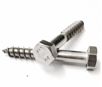
DIN 571 Hex Head Wood Screws (Coach Screws): Manufacturer & Distributor
A coach screw is a big wood screw with a hexagon head. It is driven with a spanner into a pilot hole and clamps a bracket, plate or board to timber from one side, with no nut.
Exotic Alloy manufactures coach screws in Mumbai, India, for timber builders, deck and fencing contractors, carpenters and pallet makers. We supply across India and to Ireland, the UK, Europe, the Gulf and Africa. Heads are cold forged and threads rolled; steel screws are zinc plated or hot-dip galvanized.
Metric and inch
This page covers metric DIN 571 coach screws and the Eurocode 5 way of rating them. For inch lag screws to ASME B18.2.1 and the US NDS withdrawal method see lag bolts; for screws with a machine thread on one end see hanger bolts.
- Head
- Hexagon, spanner 7–30 mm
- Thread
- Wood thread, b ≥ 0.6 l, gimlet point
- Length
- Under the head
- Fixing
- One side, into a pilot hole
- Design
- EN 1995-1-1 with EN 14592 values
- Related
- Lag bolts, hanger bolts, washers
Coach Screw Specification
The range we manufacture and supply.
Coach Screw vs Through-Bolt vs Carriage Bolt
Three ways to fix to a timber beam.
| Fastener | Access | Holds by | Best for |
|---|---|---|---|
| Coach screw | One side | Wood thread in the timber | Brackets, ledgers, posts to walls |
| Hex bolt + nut | Both sides | Clamping through the timber | Heavy beams, frames |
| Carriage bolt + nut | Both sides | Clamping; neck locks in the wood | Smooth, tamper-resistant faces |
| Lag screw (inch) | One side | Wood thread | US-designed projects, NDS values |
Coach Screw Dimensions & Weights (DIN 571)
| d nominal | d min | s across flats spanner | k head height | e across corners min | Thread length b ≥ 0.6 l | Lengths in DIN 571 mass table |
|---|---|---|---|---|---|---|
| 4 | 3.52 | 7 | 2.8 | 7.5 | 0.6 × l | 16–40 mm |
| 5 | 4.52 | 8 | 3.5 | 8.63 | 0.6 × l | 16–50 mm |
| 6 | 5.52 | 10 | 4 | 10.89 | 0.6 × l | 20–80 mm |
| 7 | 6.42 | 12 | 5 | 13.07 | 0.6 × l | to order |
| 8 | 7.42 | 13 | 5.5 | 14.2 | 0.6 × l | 25–100 mm |
| 10 | 9.42 | 17 | 7 | 18.72 | e.g. l 100 → b ≥ 60 | 30–100 mm |
| 12 | 11.3 | 19 | 8 | 20.88 | 0.6 × l | 35–120 mm |
| 16 | 15.3 | 24 | 10 | 26.17 | 0.6 × l | 50–160 mm |
| 20 | 19.3 | 30 | 13 | 32.95 | 0.6 × l | 60–200 mm |
DIN 571:2016, mm. Thread length at least 0.6 times the nominal length, measured under the head.
| l, mm | d 4 | d 5 | d 6 | d 8 | d 10 | d 12 | d 16 | d 20 |
|---|---|---|---|---|---|---|---|---|
| 20 | 2.01 | 3.42 | 5.02 | – | – | – | – | – |
| 30 | 2.81 | 4.62 | 6.62 | 12.9 | 23.6 | – | – | – |
| 40 | 3.51 | 5.82 | 8.22 | 15.6 | 28 | 39.2 | – | – |
| 50 | – | 7.03 | 9.64 | 18.2 | 32.1 | 45.4 | 84.1 | – |
| 60 | – | – | 11.2 | 20.9 | 36.5 | 51.8 | 94.9 | 165 |
| 80 | – | – | 14.32 | 26.5 | 45.2 | 64.5 | 118 | 201 |
| 100 | – | – | – | 32 | 54 | 77.1 | 141 | 238 |
| 120 | – | – | – | – | – | 89.5 | 163 | 275 |
| 160 | – | – | – | – | – | – | 209 | 348 |
| 200 | – | – | – | – | – | – | – | 421 |
DIN 571 approximate mass, kg per 1,000 pieces (steel, 7.85 kg/dm³), selected lengths; stainless is about the same.
| d | Core d1 | Shank ds | Head s / k | Pre-drill d0 softwood | Hole in steel d0,steel | fax,k N/mm², ρa 370 | fhead,k N/mm², ρa 350 | Tension Rtens,k kN | My,k N·m |
|---|---|---|---|---|---|---|---|---|---|
| 6 | 4.2 | 5.4 | 10 / 4 | 4 | 6.5 | 21.9 | 22.7 | 9.19 | 11.9 |
| 8 | 5.6 | 7.3 | 13 / 5.5 | 5.5 | 8.5 | 21 | 20.9 | 13.49 | 25 |
| 10 | 7.2 | 9.5 | 17 / 7 | 7 | 10.5 | 18.3 | 21.8 | 20.73 | 44.7 |
| 12 | 9.2 | 11.5 | 19 / 8 | 8.5 | 12.5 | 15.8 | 22.9 | 25.06 | 71.9 |
Declared values of one CE marked EN 14592 hex head wood screw with DIN 571 heads and 0.6 L thread (manufacturer data sheet). Other products declare their own values; design with the values of the screw you buy.
How to Pre-Drill & Fit a Coach Screw
Coach screws over 6 mm are pre-drilled. The pilot hole lets the thread form without splitting the timber; too small and the screw shears or splits the wood, too large and it strips. Drive with a spanner or impact driver and stop when the head seats on its washer.
The thread must sit in the timber that holds the point, and for design to EN 1995-1-1 the threaded penetration should be at least six screw diameters.
| Screw d | Pilot, softwood | Hole in steel | Min. thread in timber |
|---|---|---|---|
| 6 mm | 4 mm | 6.5 mm | 36 mm (6d) |
| 8 mm | 5.5 mm | 8.5 mm | 48 mm (6d) |
| 10 mm | 7 mm | 10.5 mm | 60 mm (6d) |
| 12 mm | 8.5 mm | 12.5 mm | 72 mm (6d) |
Hole sizes declared for one EN 14592 screw; follow your screw’s declaration.
Withdrawal, Head Pull-Through & Tension (EN 1995-1-1)
An axially loaded coach screw can fail in three ways: the thread pulls out of the timber (withdrawal), the head pulls through a timber part (head pull-through), or the screw breaks (tension). The lowest governs.
EN 1995-1-1 uses values declared by the screw maker: withdrawal = fax,k × d × lef × kd × (ρk/ρa)0.8, with kd = d/8 up to 1, and head pull-through = fhead,k × dh² × (ρk/ρa)0.8, for a screw at right angles to the grain.
| Size d × L | Thread Lg 0.6 L | Withdrawal Rax,k kN | Head pull-through Rhead,k, kN | Tension Rtens,k, kN | Governs |
|---|---|---|---|---|---|
| 6 × 60 | 36 | 3.39 | 2.27 | 9.19 | head pull-through |
| 6 × 90 | 54 | 5.09 | 2.27 | 9.19 | head pull-through |
| 6 × 140 | 84 | 7.92 | 2.27 | 9.19 | head pull-through |
| 8 × 60 | 36 | 5.79 | 3.53 | 13.49 | head pull-through |
| 8 × 120 | 72 | 11.57 | 3.53 | 13.49 | head pull-through |
| 8 × 200 | 120 | 19.28 | 3.53 | 13.49 | head pull-through |
| 10 × 80 | 48 | 8.40 | 6.30 | 20.73 | head pull-through |
| 10 × 140 | 84 | 14.70 | 6.30 | 20.73 | head pull-through |
| 10 × 200 | 120 | 21.01 | 6.30 | 20.73 | head pull-through |
| 12 × 120 | 72 | 13.06 | 8.27 | 25.06 | head pull-through |
| 12 × 200 | 120 | 21.76 | 8.27 | 25.06 | head pull-through |
| 12 × 260 | 156 | 28.29 | 8.27 | 25.06 | head pull-through |
Our calculation, characteristic values, ρk 350 kg/m³, thread 0.6 L fully in the timber; it reproduces the maker’s published table within 0.5 %.
Coach Screw Axial Capacity Calculator
Pick the screw and length, the fixture thickness and the timber, then the service class and load duration for a design value.
Screw & joint
Our calculation, EN 1995-1-1 method for one screw at 90° to the grain, using the declared values of one EN 14592 hex head wood screw (d 6–12). Design Rd = min(kmod × Rk / 1.3; Rtens,k / 1.25). Not a substitute for an engineer’s design with your product’s values.
Result
Coach Screw Materials & Finishes
| Material | Finish | Best for |
|---|---|---|
| Carbon steel | Zinc plated | Indoor, dry timber |
| Carbon steel | Hot-dip galvanized | Outdoor work, fencing, treated timber |
| A2 stainless (304) | Plain, passivated | Decks, cladding, visible fixings |
| A4 stainless (316) | Plain, passivated | Coastal, marine, pools, chemical plant |
Acidic timbers such as oak and some preservative treatments corrode plain and zinc-plated steel faster; use hot-dip galvanized or stainless screws there and follow the timber or treatment supplier’s advice.
How Our Coach Screws Are Made
Wire
Steel or stainless wire, certified by heat.
Heading
Hexagon head cold forged and trimmed.
Pointing
Gimlet point formed.
Thread rolling
Wood thread rolled to 0.6 l or more.
Finishing
Zinc plating, hot-dip galvanizing or passivation.
Inspection
Head, thread and coating checked, packed by lot.
Where Our Coach Screws Are Used
Timber framing
Ledgers, joist hangers and brackets.
Decks & docks
Stainless or galvanized, outdoors.
Fencing & gates
Rails, hinges and post fixings.
Play & garden
Play frames, pergolas and furniture.
Pallets & crates
Heavy packing and skids.
Steel to timber
Plates, angles and mounting rails.
Coach Screw Inspection & Certification
| Check | Method | Applied to |
|---|---|---|
| Head s, k, e | Callipers to DIN 571 | Every lot |
| Thread length | b ≥ 0.6 l | Every lot |
| Thread and point | Profile and visual check | Every lot |
| Coating | Thickness gauge; ISO 10684 for hot-dip galvanizing | Galvanized lots |
| Driving | Trial drive into timber | Every lot |
| Material | PMI / chemical analysis | Stainless lots |
Every shipment includes
- Mill certificate with heat number
- Dimensional report
- Lot number on every box
On request
- EN 10204 3.1 certificate
- Declaration of performance (EN 14592 screws)
- Coating thickness report