Hex Lag Screws
ASME B18.2.1 · No. 10 – ⅞″The standard lag bolt, with a full-diameter body, hex head and gimlet point. NDS design values are based on this screw.
Hex lag screws to ASME B18.2.1 from No. 10 to ⅞″ and hexagon head wood screws to DIN 571 from 4 to 20 mm. Each has a coarse wood thread and a gimlet point. We supply them in low-carbon steel, hot-dip galvanized for treated lumber, and stainless 304 and 316 for decks, docks and coastal work, with export packing and certificates.
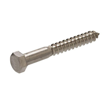
A lag bolt, properly a lag screw, is a heavy wood screw with a hex head. Its coarse, sharp thread cuts its own mating thread in timber, and it is turned into a pre-drilled lead hole with a wrench. There is no nut, so it fastens where the far side of the timber cannot be reached.
Exotic Alloy manufactures lag screws in Mumbai, India. Inch hex lag screws follow ASME B18.2.1, the standard the US National Design Specification (NDS) for Wood Construction is based on, and metric screws follow DIN 571. We supply timber builders, deck and dock contractors, pallet and crate makers, and fastener distributors in India, and export to the USA, Canada, Europe and the Gulf.
Common ¼″ to ½″ lag screws in hot-dip galvanized steel and SS 304 / 316 ship from stock. Long lengths to 16″, the larger sizes, DIN 571 metric sizes and special alloys are made to order.
The range we manufacture and supply.
The standard lag bolt, with a full-diameter body, hex head and gimlet point. NDS design values are based on this screw.
The metric lag screw for timber work in Europe, the Middle East and Asia. DIN 571 covers non-structural use. Load-bearing timber structures in Europe need screws with a product approval.
The original lag screw head, still used for restoration work, rustic timber and pole-line hardware. See also square head bolts.
A hex head with an integral washer face and threads to the head, for ledger, pallet and crate work where a separate washer is unwanted.
For pressure-treated lumber, decks, docks, piers and coastal buildings. Stainless 316 is used for marine and pool work.
For boat building, marine timber and chemical plant timber structures, made to order to the B18.2.1 or DIN 571 pattern.
| Feature | Lag screw | Carriage bolt | Proprietary structural screw |
|---|---|---|---|
| Access needed | One side only | Both sides (nut) | One side only |
| Pre-drilling | Clearance + lead hole | Through hole | Usually none (self-tapping) |
| Design basis | AWC NDS (B18.2.1 lag screws) | AWC NDS (bolts) | Product evaluation report |
| Installation | Wrench or impact driver | Spanner on nut | Drill-driver |
| Best for | Ledgers, posts, heavy timber, equipment on wood | Through-bolted joints, rails | Fast structural screwing per its report |
Inch dimensions from ASME B18.2.1 hex lag screw tables, metric from DIN 571 (12/2016).
| Size | Threads / in | Body E max / min, in | Across flats F basic (max / min), in | Across corners G max / min, in | Head height H basic (max / min), in | Shoulder S min, in |
|---|---|---|---|---|---|---|
| No. 10 | 11 | 0.199 / 0.178 | 9/32″ (0.281 / 0.271) | 0.323 / 0.309 | 1/8″ (0.140 / 0.110) | 0.094 |
| 1/4″ | 10 | 0.260 / 0.237 | 7/16″ (0.438 / 0.425) | 0.505 / 0.484 | 11/64″ (0.188 / 0.150) | 0.094 |
| 5/16″ | 9 | 0.324 / 0.298 | 1/2″ (0.500 / 0.484) | 0.577 / 0.552 | 7/32″ (0.235 / 0.195) | 0.125 |
| 3/8″ | 7 | 0.388 / 0.360 | 9/16″ (0.562 / 0.544) | 0.650 / 0.620 | 1/4″ (0.268 / 0.226) | 0.125 |
| 7/16″ | 7 | 0.452 / 0.421 | 5/8″ (0.625 / 0.603) | 0.722 / 0.687 | 19/64″ (0.316 / 0.272) | 0.156 |
| 1/2″ | 6 | 0.515 / 0.482 | 3/4″ (0.750 / 0.725) | 0.866 / 0.826 | 11/32″ (0.364 / 0.302) | 0.156 |
| 5/8″ | 5 | 0.642 / 0.605 | 15/16″ (0.938 / 0.906) | 1.083 / 1.033 | 27/64″ (0.444 / 0.378) | 0.312 |
| 3/4″ | 4½ | 0.768 / 0.729 | 1-1/8″ (1.125 / 1.088) | 1.299 / 1.240 | 1/2″ (0.524 / 0.455) | 0.375 |
| 7/8″ | 4 | 0.895 / 0.852 | 1-5/16″ (1.312 / 1.269) | 1.516 / 1.447 | 37/64″ (0.604 / 0.531) | 0.375 |
Dimensions in inches. Length tolerance: ±0.12″ up to 6″ long and ±0.25″ over 6″ for ½″ and smaller; ±0.25″ for larger sizes.
| Nominal length L in | Minimum thread length T L/2 + 0.50 or 6 in, in | Unthreaded length at most, in |
|---|---|---|
| 1 | threaded as close to the head as practicable | – |
| 1.5 | 1.25 | 0.25 |
| 2 | 1.50 | 0.50 |
| 2.5 | 1.75 | 0.75 |
| 3 | 2.00 | 1.00 |
| 3.5 | 2.25 | 1.25 |
| 4 | 2.50 | 1.50 |
| 5 | 3.00 | 2.00 |
| 6 | 3.50 | 2.50 |
| 8 | 4.50 | 3.50 |
| 10 | 5.50 | 4.50 |
| 12 | 6.00 | 6.00 |
| 14 | 6.00 | 8.00 |
| 16 | 6.00 | 10.00 |
B18.2.1 sets only the minimum thread length; body length is not a controlled dimension. Thread may run further toward the head.
| Size d mm | d min mm | Across flats s mm | Head height k mm | Across corners e min, mm | Nearest inch size for reference |
|---|---|---|---|---|---|
| 4 | 3.52 | 7 | 2.8 | 7.5 | – |
| 5 | 4.52 | 8 | 3.5 | 8.63 | – |
| 6 | 5.52 | 10 | 4 | 10.89 | 1/4″ (6.35 mm) |
| 7 | 6.42 | 12 | 5 | 13.07 | – |
| 8 | 7.42 | 13 | 5.5 | 14.2 | 5/16″ (7.94 mm) |
| 10 | 9.42 | 17 | 7 | 18.72 | 3/8″ (9.53 mm) |
| 12 | 11.3 | 19 | 8 | 20.88 | 1/2″ (12.7 mm) |
| 16 | 15.3 | 24 | 10 | 26.17 | 5/8″ (15.9 mm) |
| 20 | 19.3 | 30 | 13 | 32.95 | 3/4″ (19.1 mm) |
Dimensions in mm. Metric and inch lag screws are not interchangeable; the nearest inch size is given only to help with conversions.
A lag screw needs two holes: a clearance hole for the plain shank and a smaller lead hole for the thread. The NDS rules below are what the published design values assume.
| Size | Shank clearance hole = D, in | Lead hole, G ≤ 0.50 40–70 % of D, in | Lead hole, 0.50 < G ≤ 0.60 60–75 % of D, in | Lead hole, G > 0.60 65–85 % of D, in | Min. penetration 4D, excl. tip, in |
|---|---|---|---|---|---|
| 1/4″ | 0.250 | 0.100 – 0.175 | 0.150 – 0.188 | 0.163 – 0.212 | 1.00 |
| 5/16″ | 0.312 | 0.125 – 0.219 | 0.188 – 0.234 | 0.203 – 0.266 | 1.25 |
| 3/8″ | 0.375 | 0.150 – 0.262 | 0.225 – 0.281 | 0.244 – 0.319 | 1.50 |
| 7/16″ | 0.438 | 0.175 – 0.306 | 0.263 – 0.328 | 0.284 – 0.372 | 1.75 |
| 1/2″ | 0.500 | 0.200 – 0.350 | 0.300 – 0.375 | 0.325 – 0.425 | 2.00 |
| 5/8″ | 0.625 | 0.250 – 0.438 | 0.375 – 0.469 | 0.406 – 0.531 | 2.50 |
| 3/4″ | 0.750 | 0.300 – 0.525 | 0.450 – 0.562 | 0.488 – 0.637 | 3.00 |
| 7/8″ | 0.875 | 0.350 – 0.612 | 0.525 – 0.656 | 0.569 – 0.744 | 3.50 |
Our calculation from the NDS percentages of the shank diameter D; use the larger end of the range for larger screws. G is the specific gravity of the wood (see the withdrawal section). The NDS lets 3/8″ and smaller lag screws loaded mainly in withdrawal go in without a lead hole in wood with G ≤ 0.50, if edge distance, end distance and spacing prevent splitting.
How hard a lag screw holds depends far more on the wood than on the steel. The NDS gives the reference withdrawal value per inch of thread in side grain as W = 1800 G1.5 D0.75 (lb/in).
Reference values before NDS adjustment factors (load duration, wet service, temperature, group action). Thread penetration excludes the tapered tip. Check the steel tensile capacity at the thread root as well.
| Size | Spruce-Pine-Fir G = 0.42 | Hem-Fir G = 0.43 | Douglas Fir-Larch G = 0.50 | Southern Pine G = 0.55 | Red Oak G = 0.67 | White Oak G = 0.73 |
|---|---|---|---|---|---|---|
| 1/4″ | 173 | 179 | 225 | 260 | 349 | 397 |
| 5/16″ | 205 | 212 | 266 | 307 | 413 | 469 |
| 3/8″ | 235 | 243 | 305 | 352 | 473 | 538 |
| 7/16″ | 264 | 273 | 342 | 395 | 531 | 604 |
| 1/2″ | 291 | 302 | 378 | 437 | 587 | 668 |
| 5/8″ | 344 | 357 | 447 | 516 | 694 | 789 |
| 3/4″ | 395 | 409 | 513 | 592 | 796 | 905 |
| 7/8″ | 443 | 459 | 576 | 664 | 893 | 1016 |
Computed with the NDS equation; the figures agree with the published NDS table (for example 305 lb/in for ⅜″ and 378 lb/in for ½″ at G 0.50). Specific gravities are the NDS values for the species combinations named. Multiply by 0.75 for end grain.
For lag screws, the finish usually matters more than the steel grade. Most lag screw failures in service come from corrosion in wet or treated timber.
| Material / grade | Basis | Properties | Use |
|---|---|---|---|
| Low-carbon steel | ASTM A307 Grade A chemistry; AISI 1006–1022 | Rockwell B70–B100; no specified tensile | Standard lag screws, dry interior timber |
| Grade 5 steel | SAE J429 Grade 5 | 120 ksi min tensile (to 1″) | Fully threaded hex washer lag screws, by order |
| Stainless 18-8 / 304 | ASTM F593 chemistry | Strength from cold work | Exterior, decks, food plants |
| Stainless 316 | ASTM F593 chemistry | Strength from cold work | Coastal, marine, pools, treated lumber |
| Finish | Specification | Coating | Use |
|---|---|---|---|
| Zinc clear (trivalent) | ASTM F1941 Fe/Zn 3AN or 5AN | 3 or 5 µm | Dry interior only |
| Zinc yellow | ASTM F1941 Fe/Zn 3C or 5C | 3 or 5 µm | Dry interior only |
| Hot-dip galvanized | ASTM A153 or F2329 | 43 µm (⅜″ and under), 50 µm (over ⅜″) | Treated lumber, exterior timber, decks |
| Passivated stainless | ASTM A967 / A380 | – | 304 / 316 lag screws |
Every grade links to its datasheet on this site.
| Alloy | UNS | Condition supplied | Tensile min MPa | Yield 0.2 % min MPa | Elongation % | Why it is chosen for hex bolts |
|---|---|---|---|---|---|---|
| Inconel 625 | N06625 | Solution annealed (Grade 1) | 827 | 414 | 30 | Seawater, sour gas, cryogenic to 980 °C oxidation; subsea flange bolting |
| Inconel 718 | N07718 | Solution treated + aged (AMS 5662) | 1240 | 1035 | 12 | Highest strength to 650 °C; turbine and wellhead bolting |
| Monel 400 | N04400 | Hot-finished annealed | 517 | 207 | 35 | Seawater, hydrofluoric acid, no chloride SCC; marine and valve bolting |
| Monel K-500 | N05500 | Age hardened (AMS 4676) | 960 | 690 | 18 | Monel 400 corrosion resistance with three times the yield; pump shafts, subsea |
| Hastelloy C-276 | N10276 | Solution annealed (ASTM B574) | 690 | 283 | 40 | Wet chlorine, hot acids, mixed oxidising / reducing media; chemical reactors |
| Incoloy 825 | N08825 | Annealed (ASTM B425) | 586 | 241 | 30 | Sulphuric and phosphoric acid, sour gas (NACE MR0175); pickling plant |
| Duplex 2205 | S32205 | Solution annealed | 655 | 450 | 25 | Twice the yield of 316 with chloride SCC resistance; offshore topsides |
| Super Duplex 2507 | S32750 | Solution annealed | 750 | 550 | 15 | PREN > 40; seawater and desalination bolting |
| Titanium Grade 5 | R56400 | Annealed (ASTM B348) | 895 | 828 | 10 | Half the weight of steel, immune to seawater; aerospace and chemical |
| A-286 | S66286 | Solution treated + aged | — | — | — | Iron-base superalloy for 650 °C bolting; on request with certified values |
Bar minimums from the linked datasheets for the supply condition shown. In timber, the holding power still comes from the wood; the alloy is chosen for corrosion resistance.
Low-carbon or stainless wire received by heat with mill certificates.
Hex or square head formed on multi-station headers; large sizes are hot forged.
The gimlet point is formed by pinch-pointing or cutting before threading.
The deep, coarse lag thread is rolled to the point, so the thread starts cutting as soon as the tip enters the lead hole.
Hot-dip galvanizing with spinning to keep the thread clean, zinc plating, or passivation for stainless.
Head, body and thread length gauged, coating thickness measured and hardness checked per lot.
Fixing ledgers, posts and beams where the far side cannot be reached for a nut.
Stainless 316 and galvanized lag screws in wet and marine timber.
Long lag screws for heavy timber connections and log walls.
Holding machinery and heavy loads to timber skids for transport.
Fixing brackets, insulators and hardware to wooden poles and cross-arms.
With a lag shield, fixing fixtures and equipment to concrete and brick.
| Check | Method | Applied to |
|---|---|---|
| Chemistry / PMI | Mill certificate; XRF PMI | Every heat; all stainless lots |
| Head & body | Across flats, corners, head height, body diameter | Every lot to ASME B18.2.1 or DIN 571 |
| Thread length | Against L/2 + 0.50″ (max 6″) | Every lot |
| Hardness | Rockwell B | Every lot |
| Coating | Magnetic thickness gauge; ASTM A153 / F2329 or F1941 limits | Every coated lot |
| Drive test | Driven into a lead hole in timber | Sample per lot, on request |
Tell us the standard, diameter, length, finish, quantity and packing. Our team responds within 2 to 4 business hours with pricing and lead time.