Hex Socket Countersunk Bolts
ISO 10642 / DIN 7991 · M3 – M20The common Allen countersunk screw for machines, tooling, slides and covers, in stainless or alloy steel.
Hex socket countersunk bolts to ISO 10642 and DIN 7991, M3 to M20, in A2-70 and A4-70 stainless and 8.8, 10.9 and 12.9 alloy steel. We also make 82° inch flat heads to ASME B18.3, and slotted, cross recess, hexalobular and square neck countersunk bolts. This page includes the countersink chart and a calculator for flush heads.
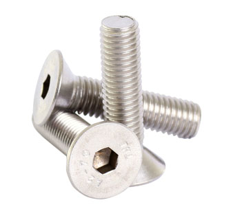
A countersunk bolt has a cone-shaped head that sinks into a matching countersink. The head ends flush with the surface, leaving nothing to catch, snag or interfere with moving parts. The cone also centres the part on the bolt.
Exotic Alloy manufactures countersunk bolts in Mumbai, India, for machine builders, tool rooms, automation, marine and architectural fabricators. We supply across India and distribute to Italy, Europe, the Gulf and Africa. The stainless A2-70 screws in the photo are cold headed with the hex socket formed in the head. 8.8, 10.9 and 12.9 alloy steel versions are hardened and tempered.
The length includes the head. Metric heads are 90° and inch heads 82°. And ISO 10642 heads are taller than the DIN 7991 heads they replaced, so cut the countersink for the standard you fit.
The range we manufacture and supply.
The same flush head with different drives, and one countersunk bolt with no drive at all.
The common Allen countersunk screw for machines, tooling, slides and covers, in stainless or alloy steel.
Six-lobe drive for higher torque without cam-out, suited to assembly lines and small sizes.
Machine screws for panels, hinges, fittings and electrical work.
Long or short square neck under a flat countersunk head, for timber, conveyor and agricultural parts.
| Size | Pitch P | dk theoretical sharp, max | dk actual min | k head height, max | s hex key | t socket depth, min | b thread, ref. |
|---|---|---|---|---|---|---|---|
| M3 | 0.5 | 6.72 | 5.54 | 1.86 | 2 | 1.1 | 18 |
| M4 | 0.7 | 8.96 | 7.53 | 2.48 | 2.5 | 1.4 | 20 |
| M5 | 0.8 | 11.2 | 9.43 | 3.1 | 3 | 1.75 | 22 |
| M6 | 1 | 13.44 | 11.34 | 3.72 | 4 | 2.2 | 24 |
| M8 | 1.25 | 17.92 | 15.24 | 4.96 | 5 | 2.9 | 28 |
| M10 | 1.5 | 22.4 | 19.22 | 6.2 | 6 | 3.5 | 32 |
| M12 | 1.75 | 26.88 | 23.12 | 7.44 | 8 | 4.3 | 36 |
| M14 | 2 | 30.8 | 26.52 | 8.4 | 10 | 4.5 | 42 |
| M16 | 2 | 33.6 | 29.01 | 8.8 | 10 | 4.8 | 48 |
| M20 | 2.5 | 40.32 | 35.04 | 10.16 | 12 | 5.6 | 60 |
DIN EN ISO 10642:2020, dimensions in mm. 90° head. The theoretical diameter is where the cone meets the top face if the edge were sharp; size countersinks to it. A 2026 edition of ISO 10642 has since been published.
| Size | dk max / min | k max | Head angle | s hex key | t | b l ≤ 125 / ≤ 200 / > 200 |
|---|---|---|---|---|---|---|
| M3 | 6 / 5.7 | 1.7 | 90° | 2 | 1.2 | 12 / – / – |
| M4 | 8 / 7.64 | 2.3 | 90° | 2.5 | 1.8 | 14 / – / – |
| M5 | 10 / 9.64 | 2.8 | 90° | 3 | 2.3 | 16 / – / – |
| M6 | 12 / 11.57 | 3.3 | 90° | 4 | 2.5 | 18 / 24 / – |
| M8 | 16 / 15.57 | 4.4 | 90° | 5 | 3.5 | 22 / 28 / – |
| M10 | 20 / 19.48 | 5.5 | 90° | 6 | 4.4 | 26 / 32 / 45 |
| M12 | 24 / 23.48 | 6.5 | 90° | 8 | 4.6 | 30 / 36 / 49 |
| M14 | 27 / 26.48 | 7 | 90° | 10 | 4.8 | 34 / 40 / 53 |
| M16 | 30 / 29.48 | 7.5 | 90° | 10 | 5.3 | 38 / 44 / 57 |
| M18 | 33 / 32.38 | 8 | 90° | 12 | 5.5 | 42 / 48 / 61 |
| M20 | 36 / 35.38 | 8.5 | 90° | 12 | 5.9 | 46 / 52 / 65 |
| M22 | 36 / 35.38 | 13.1 | 60° | 14 | 8.8 | 50 / 56 / 69 |
| M24 | 39 / 38.38 | 14 | 60° | 14 | 10.3 | 54 / 60 / 73 |
DIN 7991:1986, dimensions in mm. DIN 7991 has been replaced by ISO 10642 but is still widely ordered. Note the 60° heads on M22 and M24.
| Size | Threads / in UNC / UNF | A head dia. theoretical sharp, max | H head height max | Hex key | Check (A − D) / 2 tan 41° |
|---|---|---|---|---|---|
| No. 4 | 40 / 48 | 0.255 | 0.083 | 1/16″ | 0.082 |
| No. 6 | 32 / 40 | 0.307 | 0.097 | 5/64″ | 0.097 |
| No. 8 | 32 / 36 | 0.359 | 0.112 | 3/32″ | 0.112 |
| No. 10 | 24 / 32 | 0.411 | 0.127 | 1/8″ | 0.127 |
| 1/4″ | 20 / 28 | 0.531 | 0.161 | 5/32″ | 0.162 |
| 5/16″ | 18 / 24 | 0.656 | 0.198 | 3/16″ | 0.198 |
| 3/8″ | 16 / 24 | 0.781 | 0.234 | 7/32″ | 0.234 |
| 7/16″ | 14 / 20 | 0.844 | 0.234 | 1/4″ | 0.234 |
| 1/2″ | 13 / 20 | 0.938 | 0.251 | 5/16″ | 0.252 |
| 5/8″ | 11 / 18 | 1.188 | 0.324 | 3/8″ | 0.324 |
| 3/4″ | 10 / 16 | 1.438 | 0.396 | 1/2″ | 0.396 |
| 1″ | 8 / 12 | 1.938 | 0.540 | 5/8″ | 0.540 |
ASME B18.3 hex socket flat countersunk head cap screws, inches, 82° head. The last column is our check: every head height matches the cone geometry to within 0.001 in.
The keys and angles match, but the head heights don’t.
| Size | k ISO 10642 mm | k DIN 7991 mm | DIN head in an ISO-flush countersink below surface | ISO head in a DIN-flush countersink above surface | Same hex key? |
|---|---|---|---|---|---|
| M3 | 1.86 | 1.7 | 0.16 mm | 0.16 mm | Yes, 2 mm |
| M4 | 2.48 | 2.3 | 0.18 mm | 0.18 mm | Yes, 2.5 mm |
| M5 | 3.1 | 2.8 | 0.30 mm | 0.30 mm | Yes, 3 mm |
| M6 | 3.72 | 3.3 | 0.42 mm | 0.42 mm | Yes, 4 mm |
| M8 | 4.96 | 4.4 | 0.56 mm | 0.56 mm | Yes, 5 mm |
| M10 | 6.2 | 5.5 | 0.70 mm | 0.70 mm | Yes, 6 mm |
| M12 | 7.44 | 6.5 | 0.94 mm | 0.94 mm | Yes, 8 mm |
| M14 | 8.4 | 7 | 1.40 mm | 1.40 mm | Yes, 10 mm |
| M16 | 8.8 | 7.5 | 1.30 mm | 1.30 mm | Yes, 10 mm |
| M20 | 10.16 | 8.5 | 1.66 mm | 1.66 mm | Yes, 12 mm |
Our calculation from maximum head heights; real heads vary within their tolerances. In stainless or visible work, ask for the standard your drawings use.
| Size | Countersink dia. at surface = dk theoretical, mm | Clearance hole ISO 273 medium, mm | Countersink depth to the hole, mm | Thinnest plate without knife edge mm | Tool angle |
|---|---|---|---|---|---|
| M3 | 6.72 | 3.4 | 1.66 | > 1.7 | 90° |
| M4 | 8.96 | 4.5 | 2.23 | > 2.2 | 90° |
| M5 | 11.2 | 5.5 | 2.85 | > 2.9 | 90° |
| M6 | 13.44 | 6.6 | 3.42 | > 3.4 | 90° |
| M8 | 17.92 | 9 | 4.46 | > 4.5 | 90° |
| M10 | 22.4 | 11 | 5.70 | > 5.7 | 90° |
| M12 | 26.88 | 13.5 | 6.69 | > 6.7 | 90° |
| M14 | 30.8 | 15.5 | 7.65 | > 7.7 | 90° |
| M16 | 33.6 | 17.5 | 8.05 | > 8.1 | 90° |
| M20 | 40.32 | 22 | 9.16 | > 9.2 | 90° |
Our calculation: depth = (countersink diameter − clearance hole) / 2 for a 90° countersink. Cut slightly larger (about 0.2 to 0.5 mm) if the head must not stand proud at its upper tolerance.
Choose the screw, the clearance hole and the plate. We work out the countersink diameter and depth for a flush or recessed head, and warn you about knife edges.
The hole defaults to ISO 273 medium (metric) or D + 1/32″ (inch). Recess is how far the head top should sit below the surface (0 = flush).
| Grade | Standard | Tensile Rm min, MPa | Yield Rp0.2 min, MPa | Hardness | Use |
|---|---|---|---|---|---|
| A2-70 | ISO 3506-1 | 700 | 450 | — | General stainless, indoor and mild outdoor |
| A4-70 | ISO 3506-1 | 700 | 450 | — | Marine, food, chemical and coastal |
| 8.8 | ISO 898-1 | 800 | 640 | 22–32 HRC | General machinery |
| 10.9 | ISO 898-1 | 1040 | 940 | 32–39 HRC | Machine tools, fixtures |
| 12.9 | ISO 898-1 | 1220 | 1100 | 39–44 HRC | Tooling and dies, black oxide |
| Alloy steel (inch) | ASTM F835 | Per ASTM F835 for socket button and flat countersunk heads | Inch flat head socket screws | ||
| Stainless (inch) | ASTM F879 | Per ASTM F879 | Inch stainless flat head screws | ||
These are the material properties of the class. Because of the reduced loadability of the countersunk head, a complete ISO 10642 screw is not expected to reach the full ISO 898-1 tensile load.
Stainless or alloy steel wire, certified by heat.
Cold heading forms the 90° or 82° cone and the drive in one piece.
Threads rolled up to the head on short lengths.
8.8, 10.9 and 12.9 hardened and tempered; stainless is not hardened.
Passivation, black oxide or zinc flake.
Head angle, height and socket gauged on every lot.
Flush heads on linear rails, wear strips and sliding surfaces.
Locating plates, jaws and inserts where nothing may stand proud.
A4 stainless countersunk bolts on decks, cleats and rails.
Balustrades, glass clamps, signage and cladding with clean, flush faces.
Smooth, cleanable surfaces with stainless countersunk screws.
Flush panels and floors; titanium where weight counts.
| Check | Method | Applied to |
|---|---|---|
| Head angle & height | Countersink gauge and height gauge | Every lot |
| Head diameter | Callipers against dk min | Every lot |
| Hex socket | Go / no-go socket gauges | Every lot |
| Thread | Ring gauges | Every lot |
| Hardness / tensile | ISO 898-1 / ISO 3506-1 | Every heat-treatment or material lot |
| Material | PMI spectrometer | Stainless lots |
Tell us the standard, drive, size, length, grade, finish and quantity. We respond within 2 to 4 business hours.