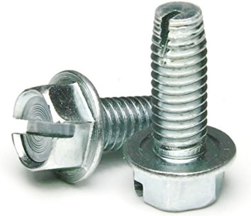
Type F, 23 & 25 Screws (Thread Cutting Screws): Manufacturer & Exporter
A thread cutting screw is a tapping screw with a slot or flutes in its tapered point. The edges cut the mating thread as the screw turns in, and the chips leave through the flute, so a plain drilled or cored hole needs no tap.
Exotic Alloy manufactures thread cutting screws in Mumbai, India, for makers of castings, enclosures, appliances and machinery, and exports them to Argentina, Latin America, the Gulf, Africa and Europe.
Cut, form or drill?
A cutting screw removes material; a thread forming screw pushes it aside; a self-drilling screw makes its own hole first. This page covers the cutting family: the six ASME points, metric DIN 7513, the hole each needs and the length that lets the point clear the part.
- Also called
- Self-tapping thread cutting screw
- Inch
- ASME B18.6.4 (now in B18.6.3): D, F, G, T, BF, BT
- Metric
- DIN 7513 (2016); DIN 7516 (withdrawn)
- Hole
- Drilled or cored, larger than a tap drill
- Steel screws
- Case hardened, HRC 45 min surface
- Related
- Thread forming, self-drilling, pan head
Thread Cutting Screw Specification
The range we manufacture and supply.
Type 1, F, G, 23, BF & 25 Cutting Points
Four points on a machine screw thread, two on the coarser spaced thread.
| ASME type | Also called | Thread | Point | Typical use |
|---|---|---|---|---|
| Type D | Type 1 | Machine screw (UNC / UNF) | Tapered, blunt; single slot with one face on the screw axis | Steel sheet, structural shapes, alloy steel, cast iron, brass, plastics |
| Type F | – | Machine screw (UNC / UNF) | Tapered, blunt; several flutes forming multiple cutting edges and chip cavities | Heavy-gauge sheet, aluminium, zinc and lead die castings, cast iron, brass, plastics |
| Type G | – | Machine screw (UNC / UNF) | Tapered, blunt; single slot centred on the axis | – |
| Type T | Type 23 | Machine screw (UNC / UNF) | Tapered, blunt; single wide flute, 90–95° included, cutting edge above the axis | Cast iron, zinc and aluminium die castings, plastics; good chip clearing, low driving torque |
| Type BF | – | Spaced (Type B) | Tapered, blunt; several flutes | – |
| Type BT | Type 25 | Spaced (Type B) | Tapered, blunt; single wide flute, 90–95° included, cutting edge above the axis | Moulded or through holes in plastics and other soft materials |
Point shapes from the ASME B18.6.4 drawings and notes; on Types T and BT the flute has a 90–95° included angle with the cutting edge above the axis. Typical uses from maker datasheets for Types 1, F, 23 and 25; we found none for G and BF. Trade names Type 1, 23 and 25 are supplier usage.
Thread Cutting Screw Dimensions
| Size | Major d max / min | Point dp ref. | Taper s, short max / min | Taper s, long max / min | Determinant L 90° / csk | Min. practical L 90° / csk | Torsion min, lb-in |
|---|---|---|---|---|---|---|---|
| No. 2-56 | .0860 / .0813 | .068 | .062 / .045 | .080 / .062 | 5/32 / 3/16 | 5/32 / 3/16 | 5 |
| No. 2-64 | .0860 / .0816 | .070 | .055 / .039 | .070 / .055 | 1/8 / 3/16 | 1/8 / 5/32 | – |
| No. 3-48 | .0990 / .0938 | .078 | .073 / .052 | .094 / .073 | 3/16 / 7/32 | 5/32 / 7/32 | – |
| No. 3-56 | .0990 / .0942 | .081 | .062 / .045 | .080 / .062 | 5/32 / 3/16 | 5/32 / 3/16 | – |
| No. 4-40 | .1120 / .1061 | .087 | .088 / .062 | .112 / .088 | 7/32 / 1/4 | 3/16 / 1/4 | 13 |
| No. 4-48 | .1120 / .1068 | .091 | .073 / .052 | .094 / .073 | 3/16 / 7/32 | 5/32 / 7/32 | – |
| No. 5-40 | .1250 / .1191 | .100 | .088 / .062 | .112 / .088 | 7/32 / 9/32 | 3/16 / 1/4 | 18 |
| No. 5-44 | .1250 / .1195 | .102 | .080 / .057 | .102 / .080 | 3/16 / 1/4 | 3/16 / 1/4 | – |
| No. 6-32 | .1380 / .1312 | .107 | .109 / .078 | .141 / .109 | 1/4 / 5/16 | 1/4 / 5/16 | 23 |
| No. 6-40 | .1380 / .1321 | .113 | .088 / .062 | .112 / .088 | 7/32 / 9/32 | 3/16 / 1/4 | – |
| No. 8-32 | .1640 / .1571 | .132 | .109 / .078 | .141 / .109 | 1/4 / 11/32 | 1/4 / 5/16 | 42 |
| No. 8-36 | .1640 / .1577 | .136 | .097 / .069 | .125 / .097 | 7/32 / 5/16 | 7/32 / 9/32 | – |
| No. 10-24 | .1900 / .1818 | .148 | .146 / .104 | .188 / .146 | 11/32 / 7/16 | 5/16 / 13/32 | 56 |
| No. 10-32 | .1900 / .1831 | .158 | .109 / .078 | .141 / .109 | 1/4 / 11/32 | 1/4 / 5/16 | 74 |
| No. 12-24 | .2160 / .2078 | .174 | .146 / .104 | .188 / .146 | 11/32 / 7/16 | 5/16 / 13/32 | 93 |
| No. 12-28 | .2160 / .2085 | .180 | .125 / .089 | .161 / .125 | 5/16 / 13/32 | 9/32 / 3/8 | – |
| 1/4-20 | .2500 / .2408 | .200 | .175 / .125 | .225 / .175 | 13/32 / 17/32 | 3/8 / 1/2 | 140 |
| 1/4-28 | .2500 / .2425 | .214 | .125 / .089 | .161 / .125 | 5/16 / 13/32 | 9/32 / 3/8 | – |
| 5/16-18 | .3125 / .3026 | .257 | .194 / .139 | .250 / .194 | 15/32 / 19/32 | 7/16 / 9/16 | 306 |
| 5/16-24 | .3125 / .3042 | .271 | .146 / .104 | .188 / .146 | 11/32 / 15/32 | 5/16 / 15/32 | – |
| 3/8-16 | .3750 / .3643 | .312 | .219 / .156 | .281 / .219 | 1/2 / 11/16 | 15/32 / 5/8 | 560 |
| 3/8-24 | .3750 / .3667 | .333 | .146 / .104 | .188 / .146 | 11/32 / 1/2 | 5/16 / 1/2 | – |
| 7/16-14 | .4375 / .4258 | .366 | .250 / .179 | .321 / .250 | 19/32 / 3/4 | 9/16 / 23/32 | – |
| 7/16-20 | .4375 / .4281 | .387 | .175 / .125 | .225 / .175 | 13/32 / 9/16 | 3/8 / 17/32 | – |
| 1/2-13 | .5000 / .4876 | .423 | .269 / .192 | .346 / .269 | 5/8 / 25/32 | 19/32 / 3/4 | 1075 |
| 1/2-20 | .5000 / .4906 | .450 | .175 / .125 | .225 / .175 | 13/32 / 9/16 | 3/8 / 17/32 | – |
ASME B18.6.4-1998 Table 8 = ASME B18.6.3-2013 Table 44, inch. Screws of the determinant length and shorter have the short point taper, longer screws the long one. Torsion: minimum torsional strength from maker datasheets for Types 1, F and 23 (identical where listed).
| Size | Threads per inch | Major d max / min | Minor d1 max / min | Point dp ref. | Taper s max / min | Min. practical L 90° / csk | Torsion min, lb-in |
|---|---|---|---|---|---|---|---|
| No. 0 | 48 | .060 / .054 | .036 / .033 | .031 | .042 / .031 | 1/8 / 1/8 | – |
| No. 1 | 42 | .075 / .069 | .049 / .046 | .044 | .048 / .036 | 1/8 / 5/32 | – |
| No. 2 | 32 | .088 / .082 | .064 / .060 | .058 | .062 / .047 | 5/32 / 3/16 | 4 |
| No. 3 | 28 | .101 / .095 | .075 / .071 | .068 | .071 / .054 | 3/16 / 7/32 | – |
| No. 4 | 24 | .114 / .108 | .086 / .082 | .079 | .083 / .063 | 3/16 / 1/4 | 13 |
| No. 5 | 20 | .130 / .123 | .094 / .090 | .087 | .100 / .075 | 7/32 / 9/32 | 18 |
| No. 6 | 20 | .139 / .132 | .104 / .099 | .095 | .100 / .075 | 1/4 / 9/32 | 24 |
| No. 7 | 19 | .154 / .147 | .115 / .109 | .105 | .105 / .079 | 1/4 / 5/16 | – |
| No. 8 | 18 | .166 / .159 | .122 / .116 | .112 | .111 / .083 | 9/32 / 11/32 | 39 |
| No. 10 | 16 | .189 / .182 | .141 / .135 | .130 | .125 / .094 | 5/16 / 3/8 | 56 |
| No. 12 | 14 | .215 / .208 | .164 / .157 | .152 | .143 / .107 | 11/32 / 7/16 | 88 |
| 1/4 in | 14 | .246 / .237 | .192 / .185 | .179 | .143 / .107 | 3/8 / 1/2 | 142 |
| 5/16 in | 12 | .315 / .306 | .244 / .236 | .230 | .167 / .125 | 15/32 / 19/32 | 290 |
| 3/8 in | 12 | .380 / .371 | .309 / .299 | .293 | .167 / .125 | 17/32 / 11/16 | 590 |
| 7/16 in | 10 | .440 / .429 | .359 / .349 | .343 | .200 / .150 | 5/8 / 25/32 | – |
| 1/2 in | 10 | .504 / .493 | .423 / .413 | .407 | .200 / .150 | 11/16 / 27/32 | – |
ASME B18.6.4-1998 Table 7 = ASME B18.6.3-2013 Table 43, inch. Torsion: Type 25 maker datasheet.
| Size | Across flats s max / min A / min B | Across corners e min A / B | Head height k nom. | k grade A max / min | k grade B max / min |
|---|---|---|---|---|---|
| M4 × 0.7 | 7 / 6.78 / 6.64 | 7.66 / 7.5 | 2.8 | 2.925 / 2.675 | 3 / 2.6 |
| M5 × 0.8 | 8 / 7.78 / 7.64 | 8.79 / 8.63 | 3.5 | 3.65 / 3.35 | 3.74 / 3.26 |
| M6 × 1 | 10 / 9.78 / 9.64 | 11.05 / 10.89 | 4 | 4.15 / 3.85 | 4.24 / 3.76 |
| M8 × 1.25 | 13 / 12.73 / 12.57 | 14.38 / 14.2 | 5.3 | 5.45 / 5.15 | 5.54 / 5.06 |
DIN 7513:2016 form A, hexagon head, mm; head dimensions as ISO 4017.
| Size | Head dk max / min | Head height k max / min | Slot n max / min | Slot depth t min | Core hole dh DIN 7513 |
|---|---|---|---|---|---|
| M2.5 × 0.45 | 4.5 / 4.32 | 1.8 / 1.66 | 0.8 / 0.66 | 0.7 | 2.2 |
| M3 × 0.5 | 5.5 / 5.32 | 2 / 1.86 | 1 / 0.86 | 0.85 | 2.7 |
| M4 × 0.7 | 7 / 6.78 | 2.6 / 2.46 | 1.51 / 1.26 | 1.1 | 3.6 |
| M5 × 0.8 | 8.5 / 8.28 | 3.3 / 3.12 | 1.51 / 1.26 | 1.3 | 4.5 |
| M6 × 1 | 10 / 9.78 | 3.9 / 3.6 | 1.91 / 1.66 | 1.6 | 5.5 |
| M8 × 1.25 | 13 / 12.73 | 5 / 4.7 | 2.31 / 2.06 | 2 | 7.4 |
DIN 7513:2016 form B, slotted cheese head, mm; head as ISO 1207. Core hole from DIN 7513:1995.
| Size | Core hole dh | % thread with dh | Tap drill d − P for comparison | DIN 7513 lengths | DIN 7516 lengths |
|---|---|---|---|---|---|
| M2.5 | 2.2 | 51 % | 2.05 (77 %) | 6–20 | – |
| M3 | 2.7 | 46 % | 2.5 (77 %) | 6–22 | 6–22 |
| M4 | 3.6 | 44 % | 3.3 (77 %) | 8–25 | 8–25 |
| M5 | 4.5 | 48 % | 4.2 (77 %) | 10–30 | 10–30 |
| M6 | 5.5 | 38 % | 5 (77 %) | 12–35 | 12–35 |
| M8 | 7.4 | 37 % | 6.75 (77 %) | 14–40 | 14–40 |
DIN 7513:1995 (types A, BE, FE, GE; A from M3) and DIN 7516:1995 (cross recessed AE, DE, EE; withdrawn): commercial lengths and core holes, mm. % thread: our calculation.
Thread Cutting vs Thread Forming
| Thread cutting | Thread forming | Self-drilling | |
|---|---|---|---|
| Hole | Drilled or cored first | Drilled or cored first | None: the point drills it |
| How the thread is made | Cut; chips leave by the flute | Material displaced; no chips | Drilled, then tapped by the thread |
| Typical materials | Cast iron, die castings, brass, plastics, heavy sheet | Ductile metals | Steel sheet |
| Standards | ASME D, F, G, T, BF, BT; DIN 7513 / 7516 | ASME A, AB, B, BP, C; DIN 7500 | ISO 15480–15483, SAE J78 |
| Our page | This page | Thread forming | Self Drilling SMS |
Hole Size, Thread Engagement & Length
Cutting screws want a bigger hole than a tap, and enough length for the point to clear.
| Size | Test plate thickness, in | Test hole drill, in | % thread test hole | Tap drill for comparison | % thread tap drill | Torsion min, lb-in |
|---|---|---|---|---|---|---|
| No. 2-56 | .0760–.0800 | #49 (.0730) | 56 % | #50 (.0700) | 69 % | 5 |
| No. 3-48 | .0920–.0960 | #46 (.0810) | 67 % | #47 (.0785) | 76 % | – |
| No. 4-40 | .1070–.1110 | #41 (.0960) | 49 % | #43 (.0890) | 71 % | 13 |
| No. 5-40 | .1070–.1110 | see note | – | #38 (.1015) | 72 % | 18 |
| No. 6-32 | .1385–.1425 | #31 (.1200) | 44 % | #36 (.1065) | 78 % | 23 |
| No. 8-32 | .1380–.1420 | #26 (.1470) | 42 % | #29 (.1360) | 69 % | 42 |
| No. 10-24 | .1845–.1905 | #17 (.1730) | 31 % | #25 (.1495) | 75 % | 56 |
| No. 12-24 | .1845–.1905 | #8 (.1990) | 31 % | #16 (.1770) | 72 % | 93 |
| 1/4-20 | .2470–.2530 | #1 (.2280) | 34 % | #7 (.2010) | 75 % | 140 |
| 5/16-18 | .3095–.3155 | L (.2900) | 31 % | F (.2570) | 77 % | 306 |
| 3/8-16 | .3720–.3780 | T (.3580) | 21 % | 5/16″ (.3125) | 77 % | 560 |
| No. 10-32 | .1845–.1905 | #16 (.1770) | 32 % | #21 (.1590) | 76 % | 74 |
| 1/4-28 | .2470–.2530 | A (.2340) | 34 % | #3 (.2130) | 80 % | – |
| 5/16-24 | .3095–.3155 | M (.2950) | 32 % | I (.2720) | 75 % | – |
| 3/8-24 | .3720–.3780 | T (.3580) | 31 % | Q (.3320) | 79 % | – |
ASME B18.6.3-2013 Table 48, Types D, F, G, T: test plate and hole for the drive test, inch. The 5-40 row is not shown: its drill (No. 37 = 0.104 in) and hole (0.1010 in) disagree. Tap drills for comparison; % thread = threads per inch × (d − hole) / 0.01299 (our calculation). Torsion from maker datasheets.
- Hole: start from the test hole or the DIN core hole and confirm it by trial in your material.
- Length: parts under the head + tapped thickness + point taper s, so full threads fill the part.
- Taper s: short taper up to the determinant length, long taper above it (ASME note).
- Blind holes: drill deeper than the screw reaches, leaving room for the point and the chips.
| Problem | Likely cause |
|---|---|
| Very high driving torque | Hole too small, or chips packing a blind hole |
| Screw strips out | Hole too large, or too little thread length |
| Head twists off | Torque above the torsional strength |
| Point will not cut | Part not 10–20 Rockwell points softer than the screw |
Thread Cutting Screw Hole & Length Finder
Thread engagement for your hole, and the shortest length that lets the point clear the part.
Screw & joint
Our calculation. Clamped = parts under the head; tapped = the part the screw threads into. Hole default: ASME drive-test hole (inch, where listed) or DIN 7513 core hole (metric). % thread = (d − hole) / (1.299 P); for the spaced thread, share of the thread depth between major and minor diameter. Inch length = parts under the head + tapped part + point taper s, not less than the minimum practical length (ASME B18.6.4). Metric: the shortest DIN length that reaches through the part; add the tapered lead.
Result
Thread Cutting Screw Materials & Hardness
| Material | Heat treatment | Hardness | Notes |
|---|---|---|---|
| Carbon steel, AISI 1016–1024 | Case hardened, liquid quenched, tempered at 650 °F (343 °C) min | Surface HRC 45 min; core HRC 28–38 | Zinc plated; the standard choice |
| 410 stainless | 1850–1950 °F (1010–1066 °C), quenched; tempered at 525 °F (274 °C) min | Core HRC 38–42 | Hardened stainless (Type F datasheet) |
| 18-8 stainless | Not hardened by heat treatment | HRB 90 to HRC 20 | Best corrosion resistance; softer materials |
| Carbon steel screw size | Case depth, in |
|---|---|
| No. 4 to No. 6 | 0.002–0.007 |
| No. 8 to No. 12 | 0.004–0.009 |
| 1/4 in and larger | 0.005–0.011 |
The material being tapped should be at least 10 to 20 Rockwell points softer than the screw. Stainless screws resist corrosion better, 18-8 more than 410. DIN 7513 screws are heat treated. Values from maker datasheets that quote the ASME B18.6.4 tables.
How Our Thread Cutting Screws Are Made
Wire
AISI 1016–1024 or stainless, certified by heat.
Heading
Head cold formed; slot or recess formed.
Thread & point
Thread rolled; tapered point slotted or fluted through the first full thread.
Hardening
Case hardened and tempered (steel), hardened (410).
Plating
Zinc plating with hydrogen embrittlement relief.
Testing
Hardness, drive and torsion tests per lot.
Where Our Thread Cutting Screws Are Used
Die castings
Zinc and aluminium housings and covers.
Cast iron
Pump, valve and machine castings.
Electrical
Enclosures, panels and cabinets.
Appliances
Plastic and metal parts, Type 25 in moulded holes.
Automotive
Brackets on heavy-gauge sheet and castings.
Machinery
Guards and covers on structural sections.
Thread Cutting Screw Inspection & Certification
| Check | Method | Applied to |
|---|---|---|
| Head and length | Callipers, gauges to ASME / DIN | Every lot |
| Thread and point | Major diameter, point diameter, taper length | Every lot |
| Slot or flutes | Visual, through the first full thread | Every lot |
| Surface and core hardness | Rockwell / micro-hardness | Every heat-treatment lot |
| Case depth | Micro-section | Every heat-treatment lot |
| Drive test | Into the ASME test plate and hole | Every lot |
| Torsional strength | Torque to failure | Every lot |
Every shipment includes
- Mill certificate with heat number
- Hardness and drive test report
- Lot number on every box
On request
- EN 10204 3.1 certificate
- Salt spray test for plated lots
- RoHS declaration