Fillister Machine Screws (ASME B18.6.3): Manufacturer & Distributor
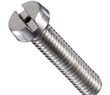
A fillister head is small across and tall: cylindrical sides, a slightly domed top and a deep slot or recess. It drops into counterbores and tight spaces where a pan head will not fit.
Exotic Alloy manufactures fillister head screws in Mumbai, India, for instrument, electrical, machinery and equipment builders. We stock across India and supply Colombia, Latin America, North America, the Gulf and Europe. Heads are cold headed and threads are rolled to UNC and UNF.
Three versions
The slotted head (ASME B18.6.3 Table 21), the Phillips head with the same head dimensions (recess per Table 22), and the slotted drilled head with a cross hole for lock wire (Table 23). The metric relative is the cheese head screw.
Fillister Head Screw Specification
The range we manufacture and supply.
Slotted, Phillips & Drilled Fillister vs Pan & Round
Narrower and taller than pan and round heads, with a deeper slot.
| Size | Fillister A × O max | Pan, slotted A × H max | Round A × H max | Fillister slot depth T max | Pan slot depth T max | Tap drill 75 % thread |
|---|---|---|---|---|---|---|
| No. 2-56 | .140 × .083 | .167 × .053 | .162 × .069 | .037 | .031 | #50 (.0700) |
| No. 4-40 | .183 × .107 | .219 × .068 | .211 × .086 | .048 | .040 | #43 (.0890) |
| No. 6-32 | .226 × .132 | .270 × .082 | .260 × .103 | .060 | .050 | #36 (.1065) |
| No. 8-32 | .270 × .156 | .322 × .096 | .309 × .120 | .071 | .058 | #29 (.1360) |
| No. 10-24 | .313 × .180 | .373 × .110 | .359 × .137 | .083 | .068 | #25 (.1495) |
| No. 12-24 | .357 × .205 | .425 × .125 | .408 × .153 | .094 | .077 | #16 (.1770) |
| 1/4″-20 | .414 × .237 | .492 × .144 | .472 × .175 | .109 | .087 | #7 (.2010) |
| 5/16″-18 | .518 × .295 | .615 × .178 | .590 × .216 | .137 | .106 | F (.2570) |
| 3/8″-16 | .622 × .355 | .740 × .212 | .708 × .256 | .164 | .124 | 5/16″ (.3125) |
| 1/2″-13 | .750 × .412 | .987 × .281 | .813 × .355 | .190 | .161 | 27/64″ (.4219) |
Inch, ASME B18.6.3 maximum values: fillister Table 21, slotted pan Table 17, round head (2002 edition). Tap drills give about 75 % thread (our check).
Fillister Head Screw Dimensions (ASME B18.6.3)
| Size | Basic dia. in | TPI UNC | A head dia. max / min | H side height max / min | O total height max / min | J slot width max / min | T slot depth max / min | Phillips driver |
|---|---|---|---|---|---|---|---|---|
| No. 0000 | .021 | – | .038 / .032 | .019 / .011 | .025 / .015 | .008 / .004 | .012 / .006 | – |
| No. 000 | .034 | – | .059 / .053 | .029 / .021 | .035 / .027 | .012 / .006 | .017 / .011 | – |
| No. 00 | .047 | – | .082 / .072 | .037 / .028 | .047 / .039 | .017 / .010 | .022 / .015 | – |
| No. 0 | .060 | 80 UNF | .096 / .083 | .043 / .038 | .055 / .047 | .023 / .016 | .025 / .015 | No. 0 |
| No. 1 | .073 | 64 | .118 / .104 | .053 / .045 | .066 / .058 | .026 / .019 | .031 / .020 | – |
| No. 2 | .086 | 56 | .140 / .124 | .062 / .053 | .083 / .066 | .031 / .023 | .037 / .025 | No. 1 |
| No. 3 | .099 | 48 | .161 / .145 | .070 / .061 | .095 / .077 | .035 / .027 | .043 / .030 | No. 1 |
| No. 4 | .112 | 40 | .183 / .166 | .079 / .069 | .107 / .088 | .039 / .031 | .048 / .035 | No. 1 |
| No. 5 | .125 | 40 | .205 / .187 | .088 / .078 | .120 / .100 | .043 / .035 | .054 / .040 | No. 2 |
| No. 6 | .138 | 32 | .226 / .208 | .096 / .086 | .132 / .111 | .048 / .039 | .060 / .045 | No. 2 |
| No. 8 | .164 | 32 | .270 / .250 | .113 / .102 | .156 / .133 | .054 / .045 | .071 / .054 | No. 2 |
| No. 10 | .190 | 24 | .313 / .292 | .130 / .118 | .180 / .156 | .060 / .050 | .083 / .064 | No. 2 |
| No. 12 | .216 | 24 | .357 / .334 | .148 / .134 | .205 / .178 | .067 / .056 | .094 / .074 | No. 3 |
| 1/4″ | .250 | 20 | .414 / .389 | .170 / .155 | .237 / .207 | .075 / .064 | .109 / .087 | No. 3 |
| 5/16″ | .312 | 18 | .518 / .490 | .211 / .194 | .295 / .262 | .084 / .072 | .137 / .110 | – |
| 3/8″ | .375 | 16 | .622 / .590 | .253 / .233 | .355 / .315 | .094 / .081 | .164 / .133 | No. 4 |
| 7/16″ | .438 | 14 | .625 / .589 | .265 / .242 | .368 / .321 | .094 / .081 | .170 / .135 | – |
| 1/2″ | .500 | 13 | .750 / .710 | .297 / .273 | .412 / .362 | .106 / .091 | .190 / .151 | – |
| 9/16″ | .562 | 12 | .812 / .768 | .336 / .308 | .466 / .410 | .118 / .102 | .214 / .172 | – |
| 5/8″ | .625 | 11 | .875 / .827 | .375 / .345 | .521 / .461 | .133 / .116 | .240 / .193 | – |
| 3/4″ | .750 | 10 | 1.000 / .945 | .441 / .406 | .612 / .542 | .149 / .131 | .281 / .226 | – |
ASME B18.6.3-2013 Table 21, inch; Phillips heads use the same head dimensions. Phillips driver sizes are shown where two sources agree; for 5/16″ ask us. No. 0 is threaded 0-80 UNF only; 0000 to 00 have special threads.
| Size | A head dia. max / min | H side height max / min | O total height max / min | J slot width max / min | T slot depth max / min | E hole location basic | F hole dia. basic (drill) |
|---|---|---|---|---|---|---|---|
| No. 2 | .140 / .124 | .062 / .055 | .083 / .070 | .031 / .023 | .030 / .022 | .026 | .031 (#68) |
| No. 3 | .161 / .145 | .070 / .064 | .095 / .082 | .035 / .027 | .034 / .026 | .030 | .037 (#63) |
| No. 4 | .183 / .166 | .079 / .072 | .107 / .094 | .039 / .031 | .038 / .030 | .035 | .037 (#63) |
| No. 5 | .205 / .187 | .088 / .081 | .120 / .106 | .043 / .035 | .042 / .033 | .038 | .046 (#56) |
| No. 6 | .226 / .208 | .096 / .089 | .132 / .118 | .048 / .039 | .045 / .035 | .043 | .046 (#56) |
| No. 8 | .270 / .250 | .113 / .106 | .156 / .141 | .054 / .045 | .065 / .054 | .043 | .046 (#56) |
| No. 10 | .313 / .292 | .130 / .123 | .180 / .165 | .060 / .050 | .075 / .064 | .043 | .046 (#56) |
| No. 12 | .357 / .334 | .148 / .139 | .205 / .188 | .067 / .056 | .087 / .074 | .053 | .046 (#56) |
| 1/4″ | .414 / .389 | .170 / .161 | .237 / .219 | .075 / .064 | .102 / .087 | .062 | .062 (1/16″) |
| 5/16″ | .518 / .490 | .211 / .201 | .295 / .276 | .084 / .072 | .130 / .110 | .078 | .070 (#50) |
| 3/8″ | .622 / .590 | .253 / .242 | .355 / .333 | .094 / .081 | .154 / .134 | .094 | .070 (#50) |
ASME B18.6.3-2013 Table 23, inch. Same head diameter and side height as Table 21, but a shallower slot and a higher minimum head height. The hole is drilled roughly at right angles to the slot, may break into the slot bottom and must be free of burrs.
Drilled Fillister Heads & Lock Wire
Where vibration could loosen a screw and a loose screw would be dangerous or costly, drilled fillister heads are tied together with stainless lock wire, or sealed with wire and a lead or plastic seal against tampering.
The holes are standard drill sizes, from 0.031″ (#68) on No. 2 to 0.070″ (#50) on 3/8″. Choose a wire that passes freely through the hole, and follow your industry’s wiring practice.
| Need | Choose |
|---|---|
| Vibration, safety-critical joint | Slotted drilled fillister + lock wire |
| Tamper evidence | Drilled fillister + seal wire |
| Power driving | Phillips fillister |
| Wider bearing face | Pan head |
| Metric design | Cheese head |
Fillister vs Metric Cheese Head (ISO 1207)
Converting a design between inch and metric? The nearest metric head is the ISO 1207 cheese head. It has a flat top and is lower, so a counterbore sized for one is not always right for the other. The threads differ, so the screws are never interchangeable.
| Inch fillister | A × O in, max | A × O mm | Nearest metric ISO 1207 cheese | dk × k mm, max | Head width fillister vs cheese |
|---|---|---|---|---|---|
| No. 2 | .140 × .083 | 3.56 × 2.11 | M2 | 3.8 × 1.4 | -0.2 mm |
| No. 4 | .183 × .107 | 4.65 × 2.72 | M3 | 5.5 × 2 | -0.9 mm |
| No. 6 | .226 × .132 | 5.74 × 3.35 | M3.5 | 6 × 2.4 | -0.3 mm |
| No. 8 | .270 × .156 | 6.86 × 3.96 | M4 | 7 × 2.6 | -0.1 mm |
| No. 10 | .313 × .180 | 7.95 × 4.57 | M5 | 8.5 × 3.3 | -0.5 mm |
| 1/4″ | .414 × .237 | 10.52 × 6.02 | M6 | 10 × 3.9 | +0.5 mm |
| 5/16″ | .518 × .295 | 13.16 × 7.49 | M8 | 13 × 5 | +0.2 mm |
| 3/8″ | .622 × .355 | 15.80 × 9.02 | M10 | 16 × 6 | -0.2 mm |
ASME B18.6.3 Table 21 and ISO 1207 maximum head sizes; pairing by nearest thread diameter and conversion are our own.
Fillister Counterbore & Tap Drill Calculator
Pick the size, set the clearance and extra depth, and get the counterbore, tap drill and head data in inch and mm.
Screw & counterbore
Our rule of thumb: counterbore diameter = A max + 2 × clearance; depth for a fully sunk head = O max + extra depth; with only the cylindrical side sunk (dome proud) = H max + extra depth. Head data from ASME B18.6.3 Table 21 (drilled heads Table 23); tap drills give about 75 % thread. Check against your own design rules.
Result
Fillister Head Screw Materials & Finishes
| Material | Finish | Best for |
|---|---|---|
| 18-8 stainless (304) | Plain, passivated | Instruments, food, outdoor and general use |
| 316 stainless | Plain, passivated | Marine, chemical and coastal plant |
| Low-carbon steel | Plain, zinc plated, black oxide | Machinery, electrical and general assembly |
| Brass | Plain, nickel plated | Electrical terminals, instruments, non-magnetic |
ASME B18.6.3: unless otherwise specified, steel machine screws are non-heat-treated low-carbon steel such as 1006 to 1022, Rockwell B69 to B100.
How Our Fillister Head Screws Are Made
Wire
Cold heading quality wire, certified by heat.
Cold heading
Tall head and Phillips recess formed in a two-blow header.
Slotting & drilling
Slots cut; cross holes drilled and deburred on drilled heads.
Thread rolling
UNC or UNF threads rolled to class 2A.
Finishing
Passivating, zinc, black oxide or nickel.
Inspection & packing
Gauged, boxed and labelled by lot.
Where Our Fillister Head Screws Are Used
Instruments
Counterbored housings, gauges and meters.
Electrical
Terminal blocks, switches and relays.
Machinery
Covers, guards and tooling in tight spaces.
Lock-wired joints
Drilled heads on vibrating equipment.
Sealed meters
Wire and seal against tampering.
Hardware & instruments
Classic slotted heads on visible parts.
Fillister Head Screw Inspection & Certification
| Check | Method | Applied to |
|---|---|---|
| Head A, H, O | Micrometer / callipers | Every lot |
| Slot J, T | Slot gauges | Slotted lots |
| Phillips recess | Penetration gauge | Phillips lots |
| Cross hole | Pin gauge, burr check | Drilled lots |
| Thread | 2A GO / NO-GO ring gauges | Every lot |
| Material | PMI / chemical analysis | Stainless and brass lots |
Every shipment includes
- Mill certificate with heat number
- Dimensional report
- Lot number on every box
On request
- EN 10204 3.1 certificate
- Salt spray test for plated lots
- First article inspection report