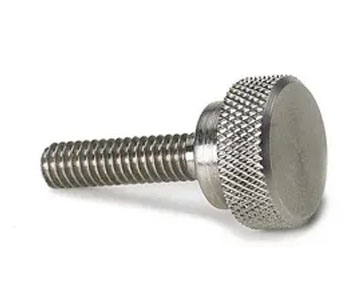
ASME B18.6.8 & DIN 464 Screws (Thumb Screws): Manufacturer & Stockist
A thumb screw has a head made for finger and thumb: a flat thumb head or a knurled knob. Panels, guards, fixtures and instruments can be opened and closed without looking for a tool.
Exotic Alloy manufactures thumb screws in Mumbai, India, and keeps common sizes in stock for machine builders, instrument and electronics makers, and maintenance teams. We supply across India and export to Norway, Scandinavia, the Gulf and Africa.
Thumb, knurled or wing?
Flat thumb heads (ASME Types A and B) and knurled heads (DIN 464 and DIN 653) are covered here. For the full DIN knurled range see knurled head screws; for two-wing heads with a longer lever see butterfly (wing) screws.
- Inch
- ASME B18.6.8 Type A; Type B regular and heavy
- Formerly
- ASME B18.17; also IFI 156
- Metric
- DIN 464 high knurled, DIN 653 low knurled
- Length
- From the bearing face
- Tightened
- By hand (DIN 464 also slotted)
- Related
- Knurled, wing screws, thumb nuts
Thumb Screw Specification
The range we manufacture and supply.
Type A, Type B & Knurled Thumb Screws
Three inch thumb heads and two metric knurled heads.
| Type | Standard | Head | Sizes |
|---|---|---|---|
| Type A, regular | ASME B18.6.8 (= B18.17, IFI 156 Table 1) | Thin round thumb head on a collar E | No. 6 to 3/8 in |
| Type B, regular | ASME B18.6.8 (= B18.17, IFI 156 Table 3) | Wide flat head, rim C thicker than the dished centre D; no collar | No. 6 to 1/2 in |
| Type B, heavy | ASME B18.6.8 (= IFI 156 Table 4) | As Type B, wider and thicker | No. 10 to 1/2 in |
| Knurled, high | DIN 464 | Knurled head on a collar; also slotted | M1 to M10 |
| Knurled, low | DIN 653 | Knurled head only | M1 to M10 (no M3.5) |
ASME B18.6.8-2010 replaced ASME B18.17; the ASME Type B tables name low-carbon steel UNS G10060.
Thumb Screw Dimensions
| Letter | Type A | Type B (regular, heavy) |
|---|---|---|
| A | Head width | Head width |
| B | Head height, bearing face to top | Head height, bearing face to top |
| C | Thumb thickness | Thickness at the rim |
| D | – | Thickness at the dished centre |
| E | Collar diameter | – |
| L | Length from the bearing face | Length from the bearing face |
| Size | Head width A max / min | Head height B max / min | Thumb thickness C max / min | Collar E max / min | Lengths L min–max |
|---|---|---|---|---|---|
| No. 6-32 | .31 / .29 | .33 / .31 | .05 / .04 | .25 / .23 | .25–.75 |
| No. 8-32 | .36 / .34 | .38 / .36 | .06 / .05 | .31 / .29 | .38–.75 |
| No. 10-24, 32 | .42 / .40 | .48 / .46 | .06 / .05 | .35 / .32 | .38–1.00 |
| No. 12-24 | .48 / .46 | .54 / .52 | .06 / .05 | .40 / .38 | .38–1.00 |
| 1/4-20 | .55 / .52 | .64 / .61 | .07 / .05 | .47 / .44 | .50–1.50 |
| 5/16-18 | .70 / .67 | .78 / .75 | .09 / .07 | .59 / .56 | .50–1.50 |
| 3/8-16 | .83 / .80 | .95 / .92 | .11 / .09 | .76 / .71 | .75–2.00 |
ASME B18.6.8-2010 Type A regular, inch; identical in ASME B18.17-1968 and IFI 156 Table 1.
| Size | Head width A max / min | Head height B max / min | Rim thickness C max / min | Centre D max / min | Lengths L min–max |
|---|---|---|---|---|---|
| No. 6-32 | .45 / .43 | .28 / .26 | .08 / .06 | .03 / .02 | .25–1.00 |
| No. 8-32 | .51 / .49 | .32 / .30 | .09 / .07 | .04 / .02 | .38–1.00 |
| No. 10-24, 32 | .58 / .54 | .39 / .36 | .10 / .08 | .05 / .03 | .38–2.00 |
| No. 12-24 | .71 / .67 | .45 / .43 | .11 / .09 | .05 / .03 | .38–2.00 |
| 1/4-20 | .83 / .80 | .52 / .48 | .16 / .14 | .06 / .03 | .50–2.50 |
| 5/16-18 | .96 / .91 | .64 / .60 | .17 / .14 | .09 / .06 | .50–3.00 |
| 3/8-16 | 1.09 / 1.03 | .71 / .67 | .22 / .18 | .11 / .08 | .75–3.00 |
| 7/16-14 | 1.40 / 1.35 | .96 / .91 | .27 / .24 | .14 / .11 | 1.00–4.00 |
| 1/2-13 | 1.54 / 1.46 | 1.09 / 1.03 | .33 / .29 | .15 / .11 | 1.00–4.00 |
ASME B18.6.8-2010 Type B regular, inch; identical in ASME B18.17-1968 and IFI 156 Table 3. D: thickness at the dished centre, as drawn.
| Size | Head width A max / min | Head height B max / min | Rim thickness C max / min | Centre D max / min | Lengths L min–max |
|---|---|---|---|---|---|
| No. 10-24 | .89 / .83 | .78 / .66 | .18 / .16 | .08 / .06 | .50–2.00 |
| 1/4-20 | 1.05 / .99 | .81 / .72 | .24 / .22 | .11 / .09 | .50–3.00 |
| 5/16-18 | 1.21 / 1.15 | .88 / .78 | .27 / .25 | .11 / .09 | .50–4.00 |
| 3/8-16 | 1.41 / 1.34 | .94 / .84 | .30 / .28 | .14 / .12 | .50–4.00 |
| 7/16-14 | 1.59 / 1.53 | 1.00 / .91 | .36 / .34 | .14 / .12 | 1.00–3.00 |
| 1/2-13 | 1.81 / 1.72 | 1.09 / .97 | .40 / .38 | .18 / .16 | 1.00–3.00 |
ASME B18.6.8-2010 Type B heavy, inch; identical in IFI 156 Table 4.
| Size | Knurl dk | Knurl height k | DIN 464 collar ds | DIN 464 head h | DIN 464 lengths | DIN 653 lengths |
|---|---|---|---|---|---|---|
| M1 × 0.25 | 5.5 | 1.5 | 2.8 | 3.5 | 2–5 | 2–6 |
| M1.2 × 0.25 | 6 | 1.5 | 3 | 4 | 2–5 | 2–8 |
| M1.4 × 0.3 | 7 | 2 | 3.5 | 4.7 | 2–6 | 3–10 |
| M1.6 × 0.35 | 7.5 | 2 | 3.8 | 5 | 2–8 | 3–12 |
| M2 × 0.4 | 9 | 2 | 4.5 | 5.3 | 3–10 | 4–16 |
| M2.5 × 0.45 | 11 | 2.5 | 5 | 6.5 | 3–12 | 5–18 |
| M3 × 0.5 | 12 | 2.5 | 6 | 7.5 | 4–16 | 6–20 |
| M3.5 × 0.6 | 14 | 3 | 7 | 8.5 | – | – |
| M4 × 0.7 | 16 | 3.5 | 8 | 9.5 | 5–18 | 8–25 |
| M5 × 0.8 | 20 | 4 | 10 | 11.5 | 6–20 | 10–30 |
| M6 × 1 | 24 | 5 | 12 | 15 | 8–25 | 12–30 |
| M8 × 1.25 | 30 | 6 | 16 | 18 | 12–28 | 16–35 |
| M10 × 1.5 | 36 | 8 | 20 | 23 | 18–40 | 20–40 |
DIN 464:2007 and DIN 653:2006, mm; both share the knurl dk and k. Lengths are the commercial range per size. Full DIN data, slot sizes and thread run-out on our knurled head page.
Thumb, Knurled or Wing: Width & Height Compared
| Head | Width swing / grip dia., mm | Height above part mm | Character |
|---|---|---|---|
| ASME Type A thumb, 1/4 in | 13.6 | 15.9 | Thin round head on a collar |
| ASME Type B thumb, regular, 1/4 in | 20.7 | 12.7 | Wide flat head, dished |
| ASME Type B thumb, heavy, 1/4 in | 25.9 | 19.4 | Widest, thickest thumb head |
| DIN 464 knurled, high, M6 | 24.0 | 15.0 | Knurl plus collar |
| DIN 653 knurled, low, M6 | 24.0 | 5.0 | Knurl only, lowest profile |
| DIN 316 wing screw, M6 | 31.5 | 16.0 | For comparison: two wings |
| ASME Type A wing, regular, 1/4 in | 30.1 | 15.1 | For comparison: two wings |
Mean values from ASME B18.6.8, DIN 464, DIN 653 and DIN 316, converted to mm. A wider head gives more leverage for the same finger force; a lower head stands out less.
Room to Turn, Length & Fit
- Room: keep walls at least half the head width from the axis, plus room for finger and thumb.
- Length: measured from the bearing face; parts clamped plus the thread engagement you need.
- Standard lengths: ASME gives a range per size; DIN 464 and DIN 653 list commercial lengths.
- Washer: a plain washer under the head protects painted or soft parts.
| Need | Better choice |
|---|---|
| Least room around the screw | ASME Type A thumb screw |
| Lowest head | DIN 653 low knurled |
| Best grip with a thumb head | ASME Type B heavy |
| Hand and screwdriver | DIN 464 slotted |
| Longest lever by hand | Wing screw |
Thumb Screw Clearance & Length Finder
Check the room to turn and find the shortest standard length.
Screw & space
Our calculation. Clamped = parts under the head; engaged = thread length you want in the tapped hole or nut; to wall = distance from the screw axis to the nearest wall or flange. Swing diameter = maximum head width (ASME A, DIN dk). Length = clamped + engaged, rounded up to the next DIN commercial length, or to the next 1/16 in inside the ASME length range.
Result
Thumb Screw Materials & Finishes
| Material | Finish | Where |
|---|---|---|
| Low-carbon steel (ASME Type B: UNS G10060) | Zinc plated | Indoor machinery, fixtures and panels |
| Stainless A2 (304) | Plain | Instruments, food equipment, as in the photo |
| Stainless A4 (316) | Plain | Outdoor, marine and washdown |
| Brass | Natural | Electrical and decorative uses |
How Our Thumb Screws Are Made
Material
Wire or bar, certified by heat.
Head
Thumb head formed; knurled heads headed or turned.
Knurl or trim
Knurl rolled; thumb heads trimmed and edges rounded.
Thread
Thread rolled.
Finishing
Zinc plating, or cleaning and passivation.
Packing
Counted boxes, lot-labelled.
Where Our Thumb Screws Are Used
Panels & enclosures
Access covers opened for service.
Instruments
Adjusters and clamps on lab and optical equipment.
Jigs & fixtures
Stops and quick clamps.
Electronics
Rack equipment, cards and connectors.
Food machinery
Stainless screws on parts removed for cleaning.
Machine guards
Guards opened for setting and cleaning.
Thumb Screw Inspection & Certification
| Check | Method | Applied to |
|---|---|---|
| Head width and height | Callipers to ASME / DIN | Every lot |
| Thumb thickness, collar | Callipers | Every lot |
| Knurl, burrs, edges | Visual | Every lot |
| Thread | Ring gauges | Every lot |
| Length | Height gauge | Every lot |
| Material | PMI / chemical analysis | Stainless and brass |
Every shipment includes
- Mill certificate with heat number
- Dimensional report
- Lot number on every box
On request
- EN 10204 3.1 certificate
- Salt spray test for plated lots
- RoHS declaration