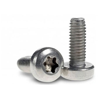
Type AB, B & DIN 7500 (Thread Forming Screws): Manufacturer & Supplier
A thread forming screw rolls its own mating thread into a plain hole. The material of the hole is displaced and strain-hardened, not cut, so there are no chips and the material around the thread is not interrupted.
Exotic Alloy manufactures thread forming screws in Mumbai, India, and supplies them to makers of enclosures, appliances, electronics, automotive parts and castings across India and abroad, including Sweden and the rest of Europe, the Gulf and Africa.
Two families
Metric DIN 7500 thread rolling screws have a trilobular body and an ISO metric thread, in seven head forms. Inch ASME tapping screws come with a gimlet point (A, AB), a blunt point (B), a cone point (BP) or a machine screw thread (C). For screws that cut instead, see thread cutting screws; for screws that drill their own hole, self-drilling screws.
- Also called
- Thread rolling screw, tapping screw
- Metric
- DIN 7500-1 forms CE–QE; holes DIN 7500-2
- Inch
- ASME B18.6.4 (now B18.6.3): A, AB, B, BP, C
- Hole
- Drilled, cast or punched; no tapping
- DIN 7500 lead
- At most 4 pitches
- Related
- Thread cutting, pan head, countersunk
Thread Forming Screw Specification
The range we manufacture and supply.
DIN 7500 Forms & ASME Type A, AB, B, BP, C Points
| DIN 7500 form | Head | Head as in | Sizes |
|---|---|---|---|
| CE | Cross recessed pan head | ISO 7045 | M2–M10 |
| DE | Hexagon head | ISO 4017 | M2–M12 |
| EE | Hexagon socket head cap | ISO 4762 | M2–M12 |
| NE | Cross recessed raised countersunk | ISO 7047 | M2–M10 |
| OE | Hexalobular socket head cap | ISO 14579 | M2–M12 |
| PE | Hexalobular socket pan head | ISO 14583 | M2–M10 |
| QE | Hexalobular socket raised countersunk | ISO 14584 | M2–M10 |
DIN 7500-1:2009 Table 6; dimensions not given in DIN 7500 follow the head standard named. Our photo shows form PE.
| ASME type | Thread | Point | Typical use |
|---|---|---|---|
| Type A | Type A, coarser than AB | Gimlet, 45° ± 5° | Self starting in thin (0.015–0.050 in) metal or resin-filled plywood; Type AB is recommended over A |
| Type AB | Spaced (as Type B) | Gimlet, 45° ± 5° | Self starting in thin metal or resin-filled plywood, particularly in brittle materials |
| Type B | Spaced | Blunt, incomplete entering threads | Moulded or through holes in thin metal, non-ferrous castings, plastics or resin-filled plywood |
| Type BP | Spaced | Cone, 40° ± 8° | – |
| Type C | Machine screw (UNC / UNF) | Blunt, tapered | – |
Points from the ASME B18.6.4 drawings; uses from maker datasheets for Types A, AB and B. ASME B18.6.3 also lists Type TRS thread rolling screws (Table 45), not tabulated here.
Thread Forming Screw Dimensions
| Size | Head dk max / min | Head k max / min | Hexalobular size, A ref. | Socket depth t max / min | Lead max 4P | b min long screws | Lengths mm |
|---|---|---|---|---|---|---|---|
| M2 × 0.4 | 4 / 3.7 | 1.6 / 1.46 | T6, 1.75 | 0.77 / 0.63 | 1.6 | 25 | 3–20 |
| M2.5 × 0.45 | 5 / 4.7 | 2.1 / 1.96 | T8, 2.4 | 1.04 / 0.91 | 1.8 | 25 | 3–25 |
| M3 × 0.5 | 5.6 / 5.3 | 2.4 / 2.26 | T10, 2.8 | 1.27 / 1.01 | 2 | 25 | 4–30 |
| M3.5 × 0.6 | 7 / 6.64 | 2.6 / 2.46 | T15, 3.35 | 1.33 / 1.07 | 2.4 | 38 | 5–35 |
| M4 × 0.7 | 8 / 7.64 | 3.1 / 2.92 | T20, 3.95 | 1.66 / 1.27 | 2.8 | 38 | 5–40 |
| M5 × 0.8 | 9.5 / 9.14 | 3.7 / 3.52 | T25, 4.5 | 1.91 / 1.52 | 3.2 | 38 | 6–50 |
| M6 × 1 | 12 / 11.57 | 4.6 / 4.3 | T30, 5.6 | 2.42 / 2.02 | 4 | 38 | 8–60 |
| M8 × 1.25 | 16 / 15.57 | 6 / 5.7 | T45, 7.95 | 3.18 / 2.79 | 5 | 38 | 10–60 |
| M10 × 1.5 | 20 / 19.48 | 7.5 / 7.14 | T50, 8.95 | 4.02 / 3.62 | 6 | 38 | 12–60 |
DIN 7500 form PE, mm; head and socket as ISO 14583:2011. The thread is fully formed from the lead (at most 4P) to near the head; long screws have b min of thread.
| Size | Threads per inch | Major d max / min | Minor d1 max / min | AB min. L 90° / csk | B: point dp / taper s ref. / max–min | B min. L 90° / csk | BP min. L 90° / csk | Torsion min, lb-in |
|---|---|---|---|---|---|---|---|---|
| No. 0 | 48 | .060 / .054 | .036 / .033 | 1/8 / 5/32 | .031 / .031–.042 | 1/8 / 1/8 | 5/32 / 3/16 | – |
| No. 1 | 42 | .075 / .069 | .049 / .046 | 5/32 / 3/16 | .044 / .036–.048 | 1/8 / 5/32 | 3/16 / 7/32 | – |
| No. 2 | 32 | .088 / .082 | .064 / .060 | 3/16 / 7/32 | .058 / .047–.062 | 5/32 / 3/16 | 1/4 / 9/32 | 4 |
| No. 3 | 28 | .101 / .095 | .075 / .071 | 3/16 / 1/4 | .068 / .054–.071 | 3/16 / 7/32 | 9/32 / 5/16 | 9 |
| No. 4 | 24 | .114 / .108 | .086 / .082 | 7/32 / 9/32 | .079 / .063–.083 | 3/16 / 1/4 | 5/16 / 11/32 | 13 |
| No. 5 | 20 | .130 / .123 | .094 / .090 | 1/4 / 5/16 | .087 / .075–.100 | 7/32 / 9/32 | 11/32 / 13/32 | 18 |
| No. 6 | 20 | .139 / .132 | .104 / .099 | 9/32 / 11/32 | .095 / .075–.100 | 1/4 / 9/32 | 3/8 / 7/16 | 24 |
| No. 7 | 19 | .154 / .147 | .115 / .109 | 5/16 / 3/8 | .105 / .079–.105 | 1/4 / 5/16 | 13/32 / 15/32 | 30 |
| No. 8 | 18 | .166 / .159 | .122 / .116 | 5/16 / 3/8 | .112 / .083–.111 | 9/32 / 11/32 | 7/16 / 1/2 | 39 |
| No. 10 | 16 | .189 / .182 | .141 / .135 | 3/8 / 7/16 | .130 / .094–.125 | 5/16 / 3/8 | 1/2 / 19/32 | 56 |
| No. 12 | 14 | .215 / .208 | .164 / .157 | 7/16 / 21/32* | .152 / .107–.143 | 11/32 / 7/16 | 9/16 / 21/32 | 88 |
| 1/4 in | 14 | .246 / .237 | .192 / .185 | 1/2 / 19/32 | .179 / .107–.143 | 3/8 / 1/2 | 21/32 / 3/4 | 142 |
| 5/16 in | 12 | .315 / .306 | .244 / .236 | 5/8 / 3/4 | .230 / .125–.167 | 15/32 / 19/32 | 27/32 / 31/32 | 290 |
| 3/8 in | 12 | .380 / .371 | .309 / .299 | 3/4 / 29/32 | .293 / .125–.167 | 17/32 / 11/16 | 15/16 / 1-1/8 | 590 |
| 7/16 in | 10 | .440 / .429 | .359 / .349 | 7/8 / 1-1/32 | .343 / .150–.200 | 5/8 / 25/32 | 1-1/8 / 1-1/4 | – |
| 1/2 in | 10 | .504 / .493 | .423 / .413 | 1 / 1-5/32 | .407 / .150–.200 | 11/16 / 27/32 | 1-1/4 / 1-13/32 | – |
ASME B18.6.4-1998 Tables 5 and 6 = ASME B18.6.3-2013 Tables 40 and 41, inch; taper s from the 1998 table. *No. 12 countersunk AB length as published. Torsion from maker datasheets (Types AB and B, identical). Type C has the thread and point of Types D, F, G, T: see the table on our thread cutting page.
| Size | Threads per inch | Major d max / min | Minor d1 max / min | AB thread at or below L 90° / csk | Torsion min, lb-in |
|---|---|---|---|---|---|
| No. 0 | 40 | .060 / .057 | .042 / .039 | 1/8 / 3/16 | – |
| No. 1 | 32 | .075 / .072 | .051 / .048 | 1/8 / 3/16 | – |
| No. 2 | 32 | .088 / .084 | .061 / .056 | 5/32 / 3/16 | – |
| No. 3 | 28 | .101 / .097 | .076 / .071 | 3/16 / 7/32 | – |
| No. 4 | 24 | .114 / .110 | .083 / .078 | 3/16 / 1/4 | – |
| No. 5 | 20 | .130 / .126 | .095 / .090 | 3/16 / 1/4 | – |
| No. 6 | 18 | .141 / .136 | .102 / .096 | 1/4 / 5/16 | 24 |
| No. 7 | 16 | .158 / .152 | .114 / .108 | 5/16 / 3/8 | 30 |
| No. 8 | 15 | .168 / .162 | .123 / .116 | 3/8 / 7/16 | 39 |
| No. 10 | 12 | .194 / .188 | .133 / .126 | 3/8 / 1/2 | 48 |
| No. 12 | 11 | .221 / .215 | .162 / .155 | 7/16 / 9/16 | 83 |
| No. 14 | 10 | .254 / .248 | .185 / .178 | 1/2 / 5/8 | 125 |
| No. 16 | 10 | .280 / .274 | .197 / .189 | 9/16 / 3/4 | – |
| No. 18 | 9 | .306 / .300 | .217 / .209 | 5/8 / 13/16 | – |
| No. 20 | 9 | .333 / .327 | .234 / .226 | 11/16 / 13/16 | 250 |
| No. 24 | 9 | .390 / .383 | .291 / .282 | 3/4 / 1 | 492 |
ASME B18.6.4-1998 Table E1 = ASME B18.6.3-2013 Table 42, inch. Screws of the listed length and shorter are made with the Type AB thread.
| Size | Pitch P | Major d1 max / min | Minor d2 max / min | End length y C / F / R, ref. | Former No. | Same thread as ASME spaced (AB, B) |
|---|---|---|---|---|---|---|
| ST2.2 | 0.8 | 2.24 / 2.10 | 1.63 / 1.52 | 2 / 1.6 / – | 2 | No. 2-32 |
| ST2.9 | 1.1 | 2.90 / 2.76 | 2.18 / 2.08 | 2.6 / 2.1 / – | 4 | No. 4-24 |
| ST3.3 | 1.3 | 3.30 / 3.12 | 2.39 / 2.29 | 3 / 2.5 / – | 5 | No. 5-20 |
| ST3.5 | 1.3 | 3.53 / 3.35 | 2.64 / 2.51 | 3.2 / 2.5 / 2.7 | 6 | No. 6-20 |
| ST3.9 | 1.3 | 3.91 / 3.73 | 2.92 / 2.77 | 3.5 / 2.7 / 3 | 7 | No. 7-19 |
| ST4.2 | 1.4 | 4.22 / 4.04 | 3.10 / 2.95 | 3.7 / 2.8 / 3.2 | 8 | No. 8-18 |
| ST4.8 | 1.6 | 4.80 / 4.62 | 3.58 / 3.43 | 4.3 / 3.2 / 3.6 | 10 | No. 10-16 |
| ST5.5 | 1.8 | 5.46 / 5.28 | 4.17 / 3.99 | 5 / 3.6 / 4.3 | 12 | No. 12-14 |
| ST6.3 | 1.8 | 6.25 / 6.03 | 4.88 / 4.70 | 6 / 3.6 / 5 | 14 | 1/4 in-14 |
| ST8 | 2.1 | 8.00 / 7.78 | 6.20 / 5.99 | 7.5 / 4.2 / 6.3 | 16 | 5/16 in-12 |
| ST9.5 | 2.1 | 9.65 / 9.43 | 7.85 / 7.59 | 8 / 4.2 / – | 20 | 3/8 in-12 |
ISO 1478, mm; ends C (pointed), F (flat), R (rounded). Inch match: converted maximum major and minor diameters are equal (our check); former number for information only.
How a Thread Rolling Screw Forms Its Thread
| Thread forming | Thread cutting | Self-drilling | |
|---|---|---|---|
| Hole | Drilled, cast, punched or lasered | Drilled or cored | None: the point drills it |
| How the thread is made | Material displaced and strain-hardened; no chips | Cut; chips leave by the flute | Drilled, then tapped by the thread |
| Standards | DIN 7500; ASME A, AB, B, BP, C; ISO 1478 tapping screws | ASME D, F, G, T, BF, BT; DIN 7513 | ISO 15480–15483 |
| Our page | This page | Thread cutting | Self Drilling SMS |
DIN 7500-2 Hole Sizes & ASME Test Holes
The longer the engagement, the larger the guideline hole.
| Thickness mm | M2.5 | M3 | M3.5 | M4 | M5 | M6 | M8 | M10 |
|---|---|---|---|---|---|---|---|---|
| 0.8 | 2.25 | – | – | – | – | – | – | – |
| 0.9 | 2.25 | – | – | – | – | – | – | – |
| 1 | 2.25 | 2.7 | – | – | – | – | – | – |
| 1.2 | 2.25 | 2.7 | 3.15 | – | – | – | – | – |
| 1.5 | 2.25 | 2.7 | 3.15 | 3.6 | 4.5 | – | – | – |
| 1.6 | 2.25 | 2.7 | 3.2 | 3.6 | 4.5 | – | – | – |
| 1.7 | 2.25 | 2.7 | 3.2 | 3.6 | 4.5 | – | – | – |
| 1.8 | 2.25 | 2.75 / 2.7 / 2.7 | 3.2 | 3.6 | 4.5 | – | – | – |
| 2 | 2.25 | 2.75 / 2.7 / 2.7 | 3.2 | 3.6 | 4.5 | 5.4 | – | – |
| 2.2 | 2.25 | 2.75 | 3.2 | 3.6 | 4.5 | 5.4 | 7.25 | – |
| 2.5 | 2.25 | 2.75 | 3.2 | 3.65 / 3.6 / 3.6 | 4.5 | 5.4 | 7.25 | 9.2 / – / – |
| 3 | 2.3 | 2.75 | 3.2 | 3.65 / 3.6 / 3.6 | 4.5 | 5.45 | 7.25 | 9.2 / 9.15 / 9.15 |
| 3.2 | 2.3 | 2.75 | 3.2 | 3.65 / 3.6 / 3.6 | 4.55 / 4.5 / 4.5 | 5.45 | 7.25 | 9.2 / 9.15 / 9.15 |
| 3.5 | 2.3 | 2.75 | 3.2 | 3.65 | 4.55 | 5.45 | 7.25 | 9.2 / 9.15 / 9.15 |
| 4 | 2.3 | 2.75 | 3.2 | 3.65 | 4.55 | 5.55 / 5.45 / 5.45 | 7.3 | 9.3 / 9.15 / 9.15 |
| 5 | 2.3 | 2.75 | 3.2 / 3.25 / 3.25 | 3.7 / 3.65 / 3.65 | 4.6 | 5.55 / 5.45 / 5.45 | 7.4 / 7.3 / 7.3 | 9.3 / 9.2 / 9.25 |
| 5.5 | – | 2.75 | 3.2 / 3.25 / 3.25 | 3.7 / 3.65 / 3.65 | 4.6 | 5.5* | 7.4 / 7.3 / 7.3 | 9.3 / 9.2 / 9.25 |
| 6 | – | 2.75 | – | 3.7 / 3.65 / 3.65 | 4.6 | 5.5* | 7.4 / 7.3 / 7.3 | 9.3 / 9.2 / 9.25 |
| 6.3 | – | – | – | 3.7 | 4.65 | 5.5* | 7.4 / 7.3 / 7.35 | 9.3 / 9.2 / 9.25 |
| 6.5 | – | – | – | 3.7 | 4.65 | 5.5* | 7.4 / 7.3 / 7.35 | 9.3 / 9.2 / 9.25 |
| 7 | – | – | – | 3.7 | 4.65 | 5.55 / 5.5 / 5.5 | 7.4 / 7.3 / 7.4 | 9.3 / 9.2 / 9.3 |
| 7.5 | – | – | – | 3.7 | 4.65 | 5.55 / 5.5 / 5.5 | 7.4 / 7.3 / 7.4 | 9.4 / 9.3 / 9.3 |
| 8 to ≤ 10 | – | – | – | – | 4.65 | 5.55 | 7.4 / 7.3 / 7.4 | 9.4 / 9.3 / 9.3 |
| > 10 to ≤ 12 | – | – | – | – | – | – | 7.5 | 9.5 / 9.4 / 9.4 |
| > 12 to ≤ 15 | – | – | – | – | – | – | 7.5 | 9.5 / 9.4 / 9.4 |
DIN 7500-2 guideline hole diameters dh, mm, tolerance H11, by material thickness or length of engagement. One value applies to steel, aluminium and copper alloys; three values are St / Al / Cu. *M6 steel 5.5 mm as in the copy we used, below the 4–5 mm value. The M10 15–20 mm row was unreadable and is left out. Verify holes by testing the actual parts.
| Type | Size | Test plate in | Test hole drill, in | % thread test hole |
|---|---|---|---|---|
| AB, B, BP | No. 4-24 | .0460–.0500 | #44 (.0860) | 100 % of depth |
| AB, B, BP | No. 6-20 | .0730–.0770 | #32 (.1160) | 66 % of depth |
| AB, B, BP | No. 8-18 | .0730–.0770 | #29 (.1360) | 68 % of depth |
| AB, B, BP | No. 10-16 | .1230–.1270 | #21 (.1590) | 62 % of depth |
| AB, B, BP | No. 12-14 | .1230–.1270 | 3/16 (.1875) | 54 % of depth |
| AB, B, BP | 1/4-14 | .1845–.1905 | 5.5 mm (.2165) | 55 % of depth |
| AB, B, BP | 5/16-12 | .1845–.1905 | I (.2720) | 61 % of depth |
| AB, B, BP | 3/8-12 | .1845–.1905 | 21/64 (.3281) | 73 % of depth |
| C | No. 4-40 | .0460–.0500 | #41 (.0960) | 49 % |
| C | No. 6-32 | .0730–.0770 | #31 (.1200) | 44 % |
| C | No. 8-32 | .0730–.0770 | #27 (.1440) | 49 % |
| C | No. 10-24 | .1230–.1270 | #19 (.1660) | 44 % |
| C | No. 10-32 | .1230–.1270 | 11/64 (.1719) | 45 % |
| C | No. 12-24 | .1230–.1270 | #11 (.1910) | 46 % |
| C | 1/4-20 | .1845–.1905 | 7/32 (.2188) | 48 % |
| C | 1/4-28 | .1845–.1905 | #1 (.2280) | 47 % |
| C | 5/16-18 | .1845–.1905 | J (.2770) | 49 % |
| C | 3/8-16 | .1845–.1905 | R (.3390) | 44 % |
| A | No. 8-15 | .0730–.0770 | #29 (.1360) | 71 % of depth |
| A | No. 10-12 | .1230–.1270 | #21 (.1590) | 57 % of depth |
| A | No. 12-11 | .1230–.1270 | 3/16 (.1875) | 57 % of depth |
| A | No. 14-10 | .1230–.1270 | 5.5 mm (.2165) | 54 % of depth |
ASME B18.6.3-2013 Table 48: test plate and hole for the drive test, inch. % thread: Type C = threads per inch × (d − hole) / 0.01299; spaced and Type A threads = share of the depth between major and minor diameter (our calculation).
Thread Forming Screw Hole & Length Finder
The guideline hole for your part and the shortest length that fills it with full threads.
Screw & part
Our calculation. Clamped = parts under the head; engaged = thickness of the part the screw forms its thread in. Metric: DIN 7500-2 guideline hole for the first table thickness at or above yours, H11; length = clamped + engaged + lead (4P), next form PE length, steel mass per 1000 from the PE table. Inch: ASME drive-test hole and plate; length = clamped + engaged + point taper s (Types B, BP, C), not less than the minimum practical length. % thread as in the tables above.
Result
Thread Forming Screw Materials & Hardness
| Screw | Material | Hardness | Notes |
|---|---|---|---|
| DIN 7500 | Cold extrusion steel, case hardened | Surface ≥ 450 HV 0.3; core 290–370 HV 10 | Zinc plated |
| ASME A, AB, B (steel) | AISI 1016–1024; liquid quenched, tempered at 650 °F (343 °C) min | Surface HRC 45 min; core HRC 28–38 | Zinc plated |
| ASME A, AB, B (stainless) | 18-8 austenitic stainless | – | General atmospheric corrosion resistance |
| Thread rolling, stainless | A2 or A4 | – | A2 for indoor assembly into plastics, sheet metal or castings; A4 outdoors and in washdown |
| ASME steel screw size | Case depth, in |
|---|---|
| No. 4 to No. 6 | 0.002–0.007 |
| No. 8 to No. 12 | 0.004–0.009 |
| 1/4 in and larger | 0.005–0.011 |
DIN 7500 hardness from the DIN 7500 material note; ASME values and the 18-8 note from maker datasheets for Types A, AB and B; A2 / A4 use from a stainless thread rolling screw supplier. Fastening stainless screws into aluminium or steel can set up galvanic corrosion in some environments.
How Our Thread Forming Screws Are Made
Wire
Cold extrusion steel or stainless, certified by heat.
Heading
Head and drive cold formed.
Thread & lead
Trilobular or spaced thread rolled with its lead or point.
Hardening
Case hardened and tempered (steel).
Plating
Zinc plating with hydrogen embrittlement relief.
Testing
Hardness, drive and torsion tests per lot.
Where Our Thread Forming Screws Are Used
Castings
Cast blind holes and rim holes, proven on trial parts.
Sheet metal
Rim holes and drilled, lasered or punched panels.
Electronics
Enclosures and chassis on assembly lines.
Appliances
Plastic and metal housings, Type B in moulded holes.
Automotive
Brackets, trims and housings.
Plywood & panels
Types A and AB in resin-filled plywood.
Thread Forming Screw Inspection & Certification
| Check | Method | Applied to |
|---|---|---|
| Head and drive | Callipers, gauges to the head standard | Every lot |
| Thread and lead | Thread and point dimensions | Every lot |
| Surface and core hardness | Vickers / Rockwell | Every heat-treatment lot |
| Case depth | Micro-section | Every heat-treatment lot |
| Drive test | Into the test plate and hole | Every lot |
| Torsional strength | Torque to failure | Every lot |
Every shipment includes
- Mill certificate with heat number
- Hardness and drive test report
- Lot number on every box
On request
- EN 10204 3.1 certificate
- Salt spray test for plated lots
- RoHS declaration