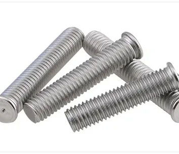
ISO 13918 PT Threaded Weld Studs (CD Weld Studs): Manufacturer & Stockist
A weld stud is fixed by welding its end to a sheet, so the sheet needs no hole and the back stays flat. The PT stud of ISO 13918 is the threaded stud for capacitor discharge (CD) welding: a short burst of current through its ignition tip welds the whole flange face in a few milliseconds.
Exotic Alloy manufactures and stocks PT weld studs in Mumbai, India, for makers of electrical cabinets, appliances, HVAC equipment, vehicles and stainless kitchen and process equipment. We supply across India and export to Vietnam, South-East Asia, the Gulf and Africa.
Thread, flange and tip
The flange (d2) is the weld area; its face is a very flat cone of 174° with the ignition tip in the centre. The length l1 leaves the tip out, and the stud loses about 0.3 mm in welding. Nuts for the studs are on our nuts page; for studs that pass through holes see full threaded studs.
- Standard
- ISO 13918:2017 (EN ISO 13918), type PT
- Process
- Capacitor discharge, tip ignition
- Sizes
- M3, M4, M5, M6, M8
- Lengths
- 6 to 30 mm (l1, tip excluded)
- After welding
- l2 ≈ l1 − 0.3 mm
- Materials
- 4.8 Cu plated, A2, A4, brass, Al, AlMg3
- Former standard
- DIN 32501
Weld Stud Specification
The range we manufacture and stock.
PT Weld Stud Dimensions, ISO 13918
Thread, flange and ignition tip for every size, mm.
| Size d1 | Pitch P | Flange d2 ±0.2 | Tip d4 ±0.08 | Tip length l3 ±0.05 | Run-out h5 max. | Flange height h1 | Face angle α | Lengths l1 +0.6 / 0 |
|---|---|---|---|---|---|---|---|---|
| M3 | 0.5 | 4.5 | 0.60 | 0.55 | 0.6 | 0.7–1.4 | 174° ±2° | 6, 8, 10, 12, 16, 20 |
| M4 | 0.7 | 5.5 | 0.65 | 0.55 | 0.6 | 0.7–1.4 | 174° ±2° | 8, 10, 12, 16, 20, 25 |
| M5 | 0.8 | 6.5 | 0.75 | 0.80 | 1 | 0.7–1.4 | 174° ±2° | 10, 12, 16, 20, 25, 30 |
| M6 | 1 | 7.5 | 0.75 | 0.80 | 1 | 0.7–1.4 | 174° ±2° | 10, 12, 16, 20, 25, 30 |
| M8 | 1.25 | 9 | 0.75 | 0.85 | 1.5 | 0.8–1.4 | 174° ±2° | 12, 16, 20, 25, 30 |
ISO 13918:2017 Table 14. d2 is the diameter at the weld area (the flange), h1 the flange height, h5 the thread run-out next to the flange, l3 the tip length. Dimensions without a tolerance here follow product grade A of ISO 4759-1; for coated studs the tolerances apply before coating.
Standard Lengths & Length After Welding
| l1 before welding | M3 | M4 | M5 | M6 | M8 |
|---|---|---|---|---|---|
| 6 mm | 5.7 | – | – | – | – |
| 8 mm | 7.7 | 7.7 | – | – | – |
| 10 mm | 9.7 | 9.7 | 9.7 | 9.7 | – |
| 12 mm | 11.7 | 11.7 | 11.7 | 11.7 | 11.7 |
| 16 mm | 15.7 | 15.7 | 15.7 | 15.7 | 15.7 |
| 20 mm | 19.7 | 19.7 | 19.7 | 19.7 | 19.7 |
| 25 mm | – | 24.7 | 24.7 | 24.7 | 24.7 |
| 30 mm | – | – | 29.7 | 29.7 | 29.7 |
Cells give l2 ≈ l1 − 0.3 mm, the length standing on the sheet after welding; – = not a standard length for that size.
Reading the lengths
- l1 is the overall length before welding, without the ignition tip; tolerance +0.6 / 0 mm.
- l2 is the nominal length after welding; for PT studs it is about l1 − 0.3 mm.
- With proper control of the welding, l2 stays within ±1 mm (ISO 13918, 6.1).
- The box label states which length is meant, l1 or l2.
- Pick a length that leaves the nut fully engaged over the part you clamp.
How Capacitor Discharge Stud Welding Works
The process
- The welding unit charges a capacitor bank; the gun holds the stud with its tip on the sheet (contact method) or just above it (gap method).
- The discharge current flows through the tip, which vaporises; the arc spreads over the flange face and melts a thin layer of stud and sheet.
- The gun drives the stud into the molten layer, which solidifies at once.
- No ferrule, no shielding gas and no weld collar.
What it means for the sheet
- The weld takes a few milliseconds: welding-unit makers quote 1 to 3 ms, other references up to 6 ms.
- Made for thin sheet; equipment makers quote from about 0.5 mm. Your welding procedure (ISO 14555) sets the limit.
- With the right settings, thin sheet need not show burn-through on the back.
- Weld steel to steel, stainless to stainless, aluminium to aluminium.
ISO 13918 Weld Stud Types & Processes
| Welding process | Threaded | Unthreaded | Internal thread | Other | Ferrule / gas |
|---|---|---|---|---|---|
| Drawn arc, ceramic ferrule or shielding gas | FD, MD, PD, RD | UD | ID | ND insulation pin, SD shear connector | Ferrule (UF, PF, RF, DF) or gas |
| Short-cycle drawn arc | PS (with flange) | US | IS | – | – |
| Capacitor discharge, tip ignition | PT | UT | IT | – | – |
Stud symbols of ISO 13918:2017 Table 1. This page covers PT; we make UT and IT studs and drawn arc studs to order.
Weld Stud Finder: Dimensions & Designation
Pick size, length and material; get the weld end, the load and the order line.
Stud & order
Dimensions from ISO 13918:2017 Table 14 as on this page; l2 ≈ l1 − 0.3 mm. Our calculation: minimum tensile load of the thread = stress area × minimum Rm of the material (ISO 898-1, ISO 3506-1, ISO 13918 Table 2), not the strength of the weld; mass ≈ pitch-diameter cylinder plus flange, approximate. Sample size from ISO 13918 Table 18, taking the order as one test lot.
Result
Weld Stud Materials & Strength
| Material | Standard | Rm min. MPa | Yield MPa | Notes |
|---|---|---|---|---|
| Steel, property class 4.8, copper plated | ISO 898-1 | ≥ 420 | ReL 340 | Copper plated (C1E) unless ordered otherwise |
| Stainless A2-50 (304 family) | ISO 3506-1 | ≥ 500 | Rp0.2 210 | Usual stainless PT stud |
| Stainless A2-70 | ISO 3506-1 | ≥ 700 | Rp0.2 450 | Cold worked, higher strength |
| Stainless A4-50 (316 family) | ISO 3506-1 | ≥ 500 | Rp0.2 210 | Molybdenum stainless for chlorides |
| Stainless A4-70 | ISO 3506-1 | ≥ 700 | Rp0.2 450 | Cold worked A4 |
| Brass CuZn37 (copper-zinc, group 32) | ISO/TR 15608 | ≥ 370 | – | For brass and copper parts |
| Aluminium Al99.5 (group 21) | ISO/TR 15608 | ≥ 100 | – | For pure aluminium sheet |
| Aluminium AlMg3 / 5754 (group 22.3) | ISO/TR 15608 | ≥ 230 | – | For Al-Mg sheet |
Materials for PT studs, ISO 13918:2017 Table 2: property classes to ISO 898-1 and ISO 3506-1 (A5-50 and A5-70 also allowed), non-ferrous groups to ISO/TR 15608 (Cu-Zn group 32, aluminium group 21, Al-Mg group 22.3); CuZn37, Al99.5 and AlMg3 are the alloys we use in those groups. Only weldable materials: non-alloy steel generally up to 0.20 % carbon, no free-cutting grades.
| Size | As mm² | 4.8 Rm 420 | Class 50 Rm 500 | Class 70 Rm 700 | Brass Rm 370 | Al Rm 100 | AlMg3 Rm 230 |
|---|---|---|---|---|---|---|---|
| M3 | 5.0 | 2.11 | 2.52 | 3.52 | 1.86 | 0.50 | 1.16 |
| M4 | 8.8 | 3.69 | 4.39 | 6.15 | 3.25 | 0.88 | 2.02 |
| M5 | 14.2 | 5.96 | 7.09 | 9.93 | 5.25 | 1.42 | 3.26 |
| M6 | 20.1 | 8.45 | 10.06 | 14.09 | 7.45 | 2.01 | 4.63 |
| M8 | 36.6 | 15.38 | 18.30 | 25.63 | 13.55 | 3.66 | 8.42 |
Minimum tensile load of the threaded section, kN = As × Rm min.; our calculation (it matches the ISO 898-1 values for class 4.8). The load the welded joint carries also depends on the sheet and the weld.
How Our Weld Studs Are Made
Wire
Weldable, killed wire, certified by heat.
Head
Flange, face cone and tip cold formed.
Thread
Rolled up to the run-out at the flange.
Finish
Copper plated (4.8) or cleaned (stainless).
Inspect
Tip, flange and thread gauged per lot.
Pack
Boxed and labelled to ISO 13918.
Where Our Weld Studs Are Used
Electrical cabinets
Earthing studs and mounting points in enclosures.
Appliances
Panels of ovens, washers and cookers.
HVAC
Ducts, air handling units and housings.
Stainless equipment
Kitchen, food and pharma equipment.
Vehicles
Bus, rail and truck body panels.
Signs & nameplates
Fixings hidden behind the face.
Weld Stud Inspection & Certification
| Check | Method | Applied to |
|---|---|---|
| Ignition tip d4, l3 | Optical measurement | Every lot |
| Flange d2, h1; length l1 | Calipers, height gauge | Every lot |
| Thread | GO / NOT GO ring gauges | Every lot |
| Chemical analysis | Delivery unit or raw material, all heats | 3.1 orders (ISO 13918, 9.2) |
| Mechanical properties | To ISO 898-1, ISO 3506-1 or Table 2 | Every test lot (9.3) |
| Trial welds | Welded and bent on your sheet | On request |
Sample size for the mechanical tests
| Studs per test lot | Sample size |
|---|---|
| up to 8 000 | 2 |
| over 8 000 to 35 000 | 3 |
| over 35 000 | 5 |
ISO 13918 Table 18; every sample must meet Table 2. The tests of clause 9 apply when an EN 10204 3.1 certificate is ordered.
Every box is labelled with
- ISO 13918 and the symbol PT
- Thread × length, saying l1 or l2
- Material and finish
- Lot number for traceability
Weld studs carry no head marking; ISO 13918 puts traceability on the packaging unit.
On request
- EN 10204 3.1 / 3.2 certificates
- Dimensional reports per size
- Declarations on restricted substances