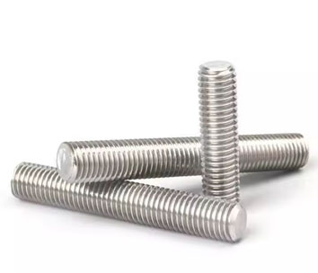
ASME B18.31.2 & DIN 976-1 Studs (Full Threaded Studs): Manufacturer & Distributor
A full threaded stud is a headless rod threaded from end to end. Two nuts clamp the joint, or one end goes into a tapped hole; because the thread runs the whole length, the nuts can sit anywhere along it.
Exotic Alloy manufactures full threaded studs in Mumbai, India, and keeps common sizes and grades in stock for refineries, pipeline and process plants, fabricators and machine builders. We supply across India and export to Kazakhstan, Central Asia, the Gulf and Africa.
Stud, stud bolt or threaded rod?
All three are threaded right through. ASME B18.31.2 calls the inch part a continuous thread stud; for pipe flanges the same kind of part is a flange bolting stud (“stud bolt”) and its length is measured differently (section 03). Metric studs follow DIN 976-1, which also lists 1, 2 and 3 m rods. For studs with a plain shank see double end, tap end and reduced shank studs; for complete flange sets see flange bolting.
- Inch
- ASME B18.31.2, 1/4 to 4 in
- Metric
- DIN 976-1 Form A / B, M2 to M72
- Thread
- UNC, UNF, 8UN; ISO coarse & fine, 6g
- Ends
- Chamfered, 1–2 pitches (ASME)
- Length
- Overall; flange studs between first full threads
- Grades
- A193 B7, B8M, A320 L7; 4.8–12.9, A2 / A4-70
- Related
- Flange bolting, double end, nuts
Full Threaded Stud Specification
The range we manufacture and supply.
Continuous Thread Stud, Stud Bolt & DIN 976-1: How Length Is Measured
The studs look alike; the length on the order means different things.
| Type | Standard | Ends | Length measured | Length tolerance |
|---|---|---|---|---|
| Continuous thread stud | ASME B18.31.2 | Chamfered, U = 1–2 pitches | LT, overall, end to end | ±0.04 to ±0.18 in |
| Flange bolting stud (stud bolt) | ASME B18.31.2, for ASME B16.5 flanges | Chamfered, U = 1–2 pitches | L, first full thread to first full thread | ±0.062 to ±0.250 in |
| Stud, Form A | DIN 976-1 | Plain | l, overall | – |
| Stud, Form B | DIN 976-1 | Chamfered | l, overall | – |
| Threaded rod, 1 / 2 / 3 m | DIN 976-1 (formerly DIN 975) | Cut | Rod length | – |
Tolerances by length band in section 04. On an order for inch studs, say whether the length is overall or first thread to first thread.
Full Threaded Stud Dimensions & Tolerances
| Size | D in | UNC thr./in | UNF thr./in | 8UN thr./in | U, UNC min–max, in | U, UNF min–max, in | U, 8UN min–max, in |
|---|---|---|---|---|---|---|---|
| 1/4 in | 0.2500 | 20 | 28 | – | .050–.100 | .036–.071 | – |
| 5/16 in | 0.3125 | 18 | 24 | – | .056–.111 | .042–.083 | – |
| 3/8 in | 0.3750 | 16 | 24 | – | .063–.125 | .042–.083 | – |
| 7/16 in | 0.4375 | 14 | 20 | – | .072–.143 | .050–.100 | – |
| 1/2 in | 0.5000 | 13 | 20 | – | .077–.154 | .050–.100 | – |
| 9/16 in | 0.5625 | 12 | 18 | – | .084–.167 | .056–.111 | – |
| 5/8 in | 0.6250 | 11 | 18 | – | .091–.182 | .056–.111 | – |
| 3/4 in | 0.7500 | 10 | 16 | – | .100–.200 | .063–.125 | – |
| 7/8 in | 0.8750 | 9 | 14 | – | .111–.222 | .072–.143 | – |
| 1 in | 1.0000 | 8 | 12 | – | .125–.250 | .084–.167 | – |
| 1-1/8 in | 1.1250 | 7 | 12 | 8 | .143–.286 | .084–.167 | .125–.250 |
| 1-1/4 in | 1.2500 | 7 | 12 | 8 | .143–.286 | .084–.167 | .125–.250 |
| 1-3/8 in | 1.3750 | 6 | 12 | 8 | .167–.333 | .084–.167 | .125–.250 |
| 1-1/2 in | 1.5000 | 6 | 12 | 8 | .167–.333 | .084–.167 | .125–.250 |
| 1-5/8 in | 1.6250 | – | – | 8 | – | – | .125–.250 |
| 1-3/4 in | 1.7500 | 5 | – | 8 | .200–.400 | – | .125–.250 |
| 1-7/8 in | 1.8750 | – | – | 8 | – | – | .125–.250 |
| 2 in | 2.0000 | 4½ | – | 8 | .222–.444 | – | .125–.250 |
| 2-1/4 in | 2.2500 | 4½ | – | 8 | .222–.444 | – | .125–.250 |
| 2-1/2 in | 2.5000 | 4 | – | 8 | .250–.500 | – | .125–.250 |
| 2-3/4 in | 2.7500 | 4 | – | 8 | .250–.500 | – | .125–.250 |
| 3 in | 3.0000 | 4 | – | 8 | .250–.500 | – | .125–.250 |
| 3-1/4 in | 3.2500 | 4 | – | 8 | .250–.500 | – | .125–.250 |
| 3-1/2 in | 3.5000 | 4 | – | 8 | .250–.500 | – | .125–.250 |
| 3-3/4 in | 3.7500 | 4 | – | 8 | .250–.500 | – | .125–.250 |
| 4 in | 4.0000 | 4 | – | 8 | .250–.500 | – | .125–.250 |
ASME B18.31.2-2014 Table 1, inch. U: chamfered thread distance from the end to the first full thread, checked with a NOT GO major-diameter ring gauge; 1 to 2 pitches at each end. Lengths in 1/4 in steps up to 10 in, 1/2 in steps above.
Continuous thread stud (overall LT)
| LT length | Tolerance in | Tolerance mm |
|---|---|---|
| 3/4 to 2-1/2 in | ±.040 | ±1.02 |
| over 2-1/2 to 4 in | ±.080 | ±2.03 |
| over 4 to 8 in | ±.100 | ±2.54 |
| over 8 to 16 in | ±.120 | ±3.05 |
| over 16 in | ±.180 | ±4.57 |
Flange bolting stud (L between first full threads)
| L length | Tolerance in | Tolerance mm |
|---|---|---|
| 3/4 to 12 in | ±.062 | ±1.57 |
| over 12 to 18 in | ±.125 | ±3.17 |
| over 18 in | ±.250 | ±6.35 |
ASME B18.31.2, inch; mm values converted.
| Size | Pitch P coarse, mm | Fine pitches mm | Stress area As mm² | Mass kg per metre | Classes DIN 976-1 |
|---|---|---|---|---|---|
| M2 | 0.4 | – | 2.1 | 0.019 | by agreement |
| M2.5 | 0.45 | – | 3.4 | 0.03 | by agreement |
| M3 | 0.5 | – | 5.0 | 0.043* | 4.8–12.9, A2/A4-70 |
| (M3.5) | 0.6 | – | 6.8 | 0.0598 | 4.8–12.9, A2/A4-70 |
| M4 | 0.7 | – | 8.8 | 0.0776 | 4.8–12.9, A2/A4-70 |
| M5 | 0.8 | – | 14.2 | 0.124 | 4.8–12.9, A2/A4-70 |
| M6 | 1 | – | 20.1 | 0.177 | 4.8–12.9, A2/A4-70 |
| M8 | 1.25 | 1 | 36.6 | 0.319 | 4.8–12.9, A2/A4-70 |
| M10 | 1.5 | 1, 1.25 | 58.0 | 0.502 | 4.8–12.9, A2/A4-70 |
| M12 | 1.75 | 1.25, 1.5 | 84.3 | 0.728 | 4.8–12.9, A2/A4-70 |
| (M14) | 2 | 1.5 | 115 | 0.995 | 4.8–12.9, A2/A4-70 |
| M16 | 2 | 1.5 | 157 | 1.33 | 4.8–12.9, A2/A4-70 |
| (M18) | 2.5 | 1.5 | 192 | 1.65 | 4.8–12.9, A2/A4-70 |
| M20 | 2.5 | 1.5 | 245 | 2.08 | 4.8–12.9, A2/A4-70 |
| (M22) | 2.5 | 1.5 | 303 | 2.56 | 4.8–12.9, A2/A4-70 |
| M24 | 3 | 2 | 353 | 3 | 4.8–12.9, A2/A4-70 |
| (M27) | 3 | 2 | 459 | 3.882 | 4.8–12.9 |
| M30 | 3.5 | 2 | 561 | 4.744 | 4.8–12.9 |
| (M33) | 3.5 | 2 | 694 | 5.812 | 4.8–12.9 |
| M36 | 4 | 3 | 817 | 6.888 | 4.8–12.9 |
| (M39) | 4 | 3 | 976 | 8.164 | 4.8–12.9 |
| M42 | 4.5 | 3 | 1121 | 9.412 | by agreement |
| (M45) | 4.5 | 3 | 1306 | 10.914 | by agreement |
| M48 | 5 | 3 | 1473 | 12.348 | by agreement |
| (M52) | 5 | 3 | 1758 | 14.654 | by agreement |
| M56 | 5.5 | 4 | 2030 | 16.946 | by agreement |
| (M60) | 5.5 | 4 | 2362 | 19.632 | by agreement |
| M64 | 6 | 4 | 2676 | 22.272 | by agreement |
| (M68) | 6 | 4 | 3055 | 25.334 | by agreement |
| M72 | – | 6 | 3460 | 28.596 | by agreement |
DIN 976-1:2016, mm; sizes in brackets are second choice. Stress area As by the ISO 898-1 formula (our calculation); mass per metre of steel stud from DIN 976-1. *M3: the pitch-diameter formula that reproduces every other row within 2 % gives 0.044 kg. M72 is listed with a 6 mm pitch only. Lengths 5–500 mm (14, 18, 22, 28, 85 and 95 mm second choice) and rods of 1, 2 and 3 m; thread tolerance 6g. Larger sizes and other classes by agreement.
Inch heavy hex nuts, ASME B18.2.2
| Size | Across flats s max, in | Height m nominal | Height m min–max, in |
|---|---|---|---|
| 1/4 in | .500 | 15/64 in | .218–.250 |
| 5/16 in | .562 | 19/64 in | .280–.314 |
| 3/8 in | .688 | 23/64 in | .341–.377 |
| 7/16 in | .750 | 27/64 in | .403–.441 |
| 1/2 in | .875 | 31/64 in | .464–.504 |
| 9/16 in | .938 | 35/64 in | .526–.568 |
| 5/8 in | 1.062 | 39/64 in | .587–.631 |
| 3/4 in | 1.250 | 47/64 in | .710–.758 |
| 7/8 in | 1.438 | 55/64 in | .833–.885 |
| 1 in | 1.625 | 63/64 in | .956–1.012 |
| 1-1/8 in | 1.812 | 1-7/64 in | 1.079–1.139 |
| 1-1/4 in | 2.000 | 1-7/32 in | 1.187–1.251 |
| 1-3/8 in | 2.188 | 1-11/32 in | 1.310–1.378 |
| 1-1/2 in | 2.375 | 1-15/32 in | 1.433–1.505 |
| 1-5/8 in | 2.562 | 1-19/32 in | 1.556–1.632 |
| 1-3/4 in | 2.750 | 1-23/32 in | 1.679–1.759 |
| 1-7/8 in | 2.938 | 1-27/32 in | 1.802–1.886 |
| 2 in | 3.125 | 1-31/32 in | 1.925–2.013 |
| 2-1/4 in | 3.500 | 2-13/64 in | 2.155–2.251 |
| 2-1/2 in | 3.875 | 2-29/64 in | 2.401–2.505 |
| 2-3/4 in | 4.250 | 2-45/64 in | 2.647–2.759 |
| 3 in | 4.625 | 2-61/64 in | 2.893–3.013 |
| 3-1/4 in | 5.000 | 3-3/16 in | 3.124–3.252 |
| 3-1/2 in | 5.375 | 3-7/16 in | 3.370–3.506 |
| 3-3/4 in | 5.750 | 3-11/16 in | 3.616–3.760 |
| 4 in | 6.125 | 3-15/16 in | 3.862–4.014 |
Metric hex nuts
| Size | ISO 4032 s / m max, mm | Heavy hex B18.2.4.6M s / m max, mm |
|---|---|---|
| M3 | 5.5 / 2.4 | – |
| M3.5 | 6 / 2.8 | – |
| M4 | 7 / 3.2 | – |
| M5 | 8 / 4.7 | – |
| M6 | 10 / 5.2 | – |
| M8 | 13 / 6.8 | – |
| M10 | 16 / 8.4 | – |
| M12 | 18 / 10.8 | 21 / 12.3 |
| M14 | 21 / 12.8 | 24 / 14.3 |
| M16 | 24 / 14.8 | 27 / 17.1 |
| M18 | 27 / 15.8 | – |
| M20 | 30 / 18 | 34 / 20.7 |
| M22 | 34 / 19.4 | 36 / 23.6 |
| M24 | 36 / 21.5 | 41 / 24.2 |
| M27 | 41 / 23.8 | 46 / 27.5 |
| M30 | 46 / 25.6 | 50 / 30.7 |
| M33 | 50 / 28.7 | – |
| M36 | 55 / 31 | 60 / 36.6 |
| M39 | 60 / 33.4 | – |
| M42 | 65 / 34 | 70 / 42 |
| M45 | 70 / 36 | – |
| M48 | 75 / 38 | 80 / 48 |
| M52 | 80 / 42 | – |
| M56 | 85 / 45 | 90 / 56 |
| M60 | 90 / 48 | – |
| M64 | 95 / 51 | 100 / 64 |
Nut heights used by the length finder. Inch: ASME B18.2.2-2022 heavy hex nuts, the usual nut for ASTM A193 / A320 studs (nut grades to ASTM A194); the 2015 edition’s 0.411 in maximum for 7/16 in is a misprint, below its own 27/64 in nominal. Metric: ISO 4032 style 1 and ASME B18.2.4.6M heavy hex nuts.
UNC or 8UN? Thread Series for Large Studs
- UNC gets coarser with size: 7 threads per inch at 1-1/8 in, 4 from 2-1/2 in up.
- 8UN keeps 8 threads per inch from 1-1/8 to 4 in; 1 in UNC already has 8.
- More metal: the shallower thread leaves 3.2 to 11.1 % more tensile stress area.
- UNF is listed only up to 1-1/2 in.
- Pipe flanges: studs are usually ordered UNC up to 1 in and 8UN from 1-1/8 in.
| Size | UNC thr./in | As UNC in² | As 8UN in² | 8UN gain % |
|---|---|---|---|---|
| 1-1/8 in | 7 | 0.763 | 0.790 | +3.6 |
| 1-1/4 in | 7 | 0.969 | 1.000 | +3.2 |
| 1-3/8 in | 6 | 1.155 | 1.234 | +6.8 |
| 1-1/2 in | 6 | 1.405 | 1.492 | +6.2 |
| 1-3/4 in | 5 | 1.899 | 2.082 | +9.6 |
| 2 in | 4½ | 2.498 | 2.771 | +10.9 |
| 2-1/4 in | 4½ | 3.248 | 3.557 | +9.5 |
| 2-1/2 in | 4 | 3.999 | 4.442 | +11.1 |
| 2-3/4 in | 4 | 4.934 | 5.425 | +10.0 |
| 3 in | 4 | 5.967 | 6.506 | +9.0 |
| 3-1/4 in | 4 | 7.099 | 7.686 | +8.3 |
| 3-1/2 in | 4 | 8.329 | 8.963 | +7.6 |
| 3-3/4 in | 4 | 9.657 | 10.339 | +7.1 |
| 4 in | 4 | 11.083 | 11.813 | +6.6 |
Stress area As = 0.7854 (D − 0.9743/n)² (ASME B1.1), our calculation. The nut must have the same thread series as the stud.
Stud Grades, Strength & Tensile Loads
Inch: ASTM A193 and A320
| Grade | Material | Diameter in | Tensile min ksi | Yield min ksi | Hardness max | Note |
|---|---|---|---|---|---|---|
| A193 B7 | 4140-type Cr-Mo, Q&T | ≤ 2½ / to 4 / to 7 | 125 / 115 / 100 | 105 / 95 / 75 | 321 HBW, 35 HRC | Standard high-temperature stud |
| A193 B7M | Cr-Mo, Q&T | ≤ 4 / to 7 | 100 / 100 | 80 / 75 | 235 HBW, 99 HRB | Hardness-limited, sour service |
| A193 B16 | Cr-Mo-V, Q&T | ≤ 2½ / to 4 / to 8 | 125 / 110 / 100 | 105 / 95 / 85 | 321 HBW, 35 HRC | Higher temperatures |
| A193 B8, B8M Cl. 1 | 304 / 316, solution treated | all | 75 | 30 | 223 HBW, 96 HRB | Corrosion and cryogenic |
| A193 B8 Cl. 2 | 304, strain hardened | ≤ ¾ / 1 / 1¼ / 1½ | 125 / 115 / 105 / 100 | 100 / 80 / 65 / 50 | 321 HBW, 35 HRC | Strength falls with size |
| A193 B8M Cl. 2 | 316, strain hardened | ≤ ¾ / 1 / 1¼ / 1½ | 110 / 100 / 95 / 90 | 95 / 80 / 65 / 50 | 321 HBW, 35 HRC | Strength falls with size |
| A320 L7 | Cr-Mo, Q&T | ≤ 2½ | 125 | 105 | 321 HBW, 35 HRC | Impact tested at −150 °F (−101 °C) |
| A320 L43 | 4340 Ni-Cr-Mo, Q&T | ≤ 4 | 125 | 105 | 321 HBW, 35 HRC | Impact tested at −150 °F (−101 °C) |
ASTM A193 (high-temperature and general service) and A320 (low-temperature service), minimum values. Austenitic Class 2 studs are strain hardened, so their strength falls as the diameter grows.
Metric: DIN 976-1 property classes
| Class | Material | Rm min MPa | Yield min MPa | DIN 976-1 sizes |
|---|---|---|---|---|
| 4.8 | Carbon steel | 420 | 340 | M3–M39 |
| 5.6 | Carbon steel | 500 | 300 | M3–M39 |
| 5.8 | Carbon steel | 520 | 420 | M3–M39 |
| 8.8 | Carbon or alloy steel, quenched & tempered | 800 (≤ M16), 830 | 640 (≤ M16), 660 | M3–M39 |
| 10.9 | Alloy steel, quenched & tempered | 1040 | 940 | M3–M39 |
| 12.9 | Alloy steel, quenched & tempered | 1220 | 1100 | M3–M39 |
| A2-70 | Stainless 304 type, cold worked | 700 | 450 | M3–M24 |
| A4-70 | Stainless 316 type, cold worked | 700 | 450 | M3–M24 |
Steel to ISO 898-1, stainless to ISO 3506-1. Yield: lower yield or 0.2 % proof stress (for 4.8 and 5.8 the ISO 898-1 stress at 0.0048 d non-proportional elongation). DIN 976-1 also allows brass (CU2, CU3) and aluminium (AL1, AL2).
| Size | As mm² | 4.8 kN | 5.6 kN | 8.8 kN | 10.9 kN | 12.9 kN | A2-70 / A4-70 kN |
|---|---|---|---|---|---|---|---|
| M6 | 20.1 | 8.4 | 10.1 | 16.1 | 20.9 | 24.5 | 14.1 |
| M8 | 36.6 | 15.4 | 18.3 | 29.3 | 38.1 | 44.7 | 25.6 |
| M10 | 58 | 24.4 | 29.0 | 46.4 | 60.3 | 70.8 | 40.6 |
| M12 | 84.3 | 35.4 | 42.2 | 67.4 | 87.7 | 102.8 | 59.0 |
| M16 | 157 | 65.9 | 78.5 | 125.6 | 163.3 | 191.5 | 109.9 |
| M20 | 245 | 102.9 | 122.5 | 203.4 | 254.8 | 298.9 | 171.5 |
| M24 | 353 | 148.3 | 176.5 | 293.0 | 367.1 | 430.7 | 247.1 |
| M30 | 561 | 235.6 | 280.5 | 465.6 | 583.4 | 684.4 | – |
| M36 | 817 | 343.1 | 408.5 | 678.1 | 849.7 | 996.7 | – |
Minimum ultimate tensile load = As × minimum tensile strength (ISO 898-1, ISO 3506-1), our calculation; 8.8 uses 830 MPa above M16. A2-70 / A4-70 only to M24 in DIN 976-1.
| Size | Thread | As in² | B7 tensile / yield kip | B8M Cl. 1 tensile / yield kip | B8M Cl. 2 tensile / yield kip |
|---|---|---|---|---|---|
| 1/2 in | 1/2-13 UNC | 0.142 | 17.7 / 14.9 | 10.6 / 4.3 | 15.6 / 13.5 |
| 5/8 in | 5/8-11 UNC | 0.226 | 28.3 / 23.7 | 17.0 / 6.8 | 24.9 / 21.5 |
| 3/4 in | 3/4-10 UNC | 0.334 | 41.8 / 35.1 | 25.1 / 10.0 | 36.8 / 31.8 |
| 7/8 in | 7/8-9 UNC | 0.462 | 57.7 / 48.5 | 34.6 / 13.9 | 46.2 / 36.9 |
| 1 in | 1-8 UNC | 0.606 | 75.7 / 63.6 | 45.4 / 18.2 | 60.6 / 48.5 |
| 1-1/8 in | 1-1/8-8UN | 0.790 | 98.8 / 83.0 | 59.3 / 23.7 | 75.1 / 51.4 |
| 1-1/4 in | 1-1/4-8UN | 1.000 | 125.0 / 105.0 | 75.0 / 30.0 | 95.0 / 65.0 |
| 1-1/2 in | 1-1/2-8UN | 1.492 | 186.5 / 156.6 | 111.9 / 44.8 | 134.3 / 74.6 |
| 1-3/4 in | 1-3/4-8UN | 2.082 | 260.3 / 218.6 | 156.2 / 62.5 | – |
| 2 in | 2-8UN | 2.771 | 346.3 / 290.9 | 207.8 / 83.1 | – |
| 2-1/2 in | 2-1/2-8UN | 4.442 | 555.3 / 466.4 | 333.2 / 133.3 | – |
| 3 in | 3-8UN | 6.506 | 748.2 / 618.1 | 488.0 / 195.2 | – |
| 3-1/2 in | 3-1/2-8UN | 8.963 | 1030.8 / 851.5 | 672.2 / 268.9 | – |
| 4 in | 4-8UN | 11.813 | 1358.5 / 1122.2 | 886.0 / 354.4 | – |
As × ASTM minimum tensile and yield strength, our calculation; UNC to 1 in, 8UN above. B8M Class 2 is covered to 1-1/2 in. 1 kip = 1,000 lbf = 4.448 kN.
Full Threaded Stud Length & Load Finder
Grip, washers, two nuts and the stick-out give the length; the grade gives the load.
Stud & joint
Our calculation. Grip = total thickness clamped (flanges and gasket, or plates); washer = thickness of one washer under each nut (0 if none); stick-out = thread beyond each nut, in pitches. Nuts: ISO 4032, or heavy hex to ASME B18.2.4.6M (metric) or B18.2.2 (inch). Ends: DIN 976-1 Form A plain, Form B chamfered; ASME studs chamfered. Inch grades are ASTM A193 unless marked A320. Length = grip + 2 washers + 2 nut heights (maximum) + 2 stick-outs, rounded up to the next DIN 976-1 length, or to the next 1/4 in (1/2 in above 10 in) as overall LT. Loads = stress area × minimum strength of the grade.
Result
Full Threaded Stud Materials & Coatings
| Material | Grades | Finish | Where |
|---|---|---|---|
| Cr-Mo alloy steel (4140 type) | ASTM A193 B7, B7M; A320 L7 | Plain, zinc, PTFE coated | Flanges, valves, pressure vessels |
| Ni-Cr-Mo alloy steel (4340) | ASTM A320 L43 | Plain, PTFE coated | Low-temperature service, larger sizes |
| Carbon and alloy steel | ISO 898-1 4.8 to 12.9 | Plain, zinc, hot-dip galvanized | Structures, machinery, anchoring |
| Stainless 304 / 316 | ASTM A193 B8, B8M; A2-70, A4-70 | Plain | Corrosive and cryogenic service |
| A-286 (iron-nickel superalloy) | ASTM A453 Grade 660 | Plain | High-temperature joints |
| Inconel 718 | ASTM A1014 (UNS N07718) | Plain | Subsea and high-temperature bolting |
| Duplex and super duplex | UNS S32205, S32750, S32760 | Plain | Seawater and offshore |
How Our Full Threaded Studs Are Made
Bar
Certified bar; B7 bar quenched and tempered.
Cut
Cut to length, ends faced square.
Thread
Thread rolled end to end; large sizes cut.
Chamfer
Ends chamfered to the root diameter.
Mark
Grade and maker’s mark on one end.
Finish
Coating, then bundling with nuts if ordered.
Where Our Full Threaded Studs Are Used
Pipe flanges
Flange joints in refineries, pipelines and process plants.
Pressure vessels
Manways, nozzles and heat exchanger channels.
Valves & pumps
Bonnets, casings and covers.
Low temperature
A320 L7 and B8 studs on cold and cryogenic lines.
Machinery
Tie rods, housings and adjustable stops.
Structures
Hangers, bracing and base plates from cut rod.
Full Threaded Stud Inspection & Certification
| Check | Method | Applied to |
|---|---|---|
| Thread | GO / NOT GO ring gauges | Every lot |
| Chamfer U | NOT GO major-diameter ring, 1–2 pitches | ASME studs |
| Length | Overall, or first thread to first thread | Every lot |
| Hardness | Brinell / Rockwell | Every heat-treat lot |
| Tensile, yield | Machined or full-size test | Per grade standard |
| Impact | Charpy V at test temperature | A320 grades |
| Material | PMI / chemical analysis | Stainless and nickel alloys |
Every shipment includes
- EN 10204 3.1 certificate with heat number
- Mechanical test and hardness results
- Dimensional report
On request
- EN 10204 3.2 with third-party inspection
- Impact tests, PMI reports
- Coating thickness reports