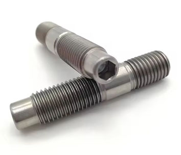
DIN 938, DIN 939 & DIN 835 Studs (Tap End Stud Bolts): Manufacturer & Exporter
A tap end stud has a short thread for a tapped hole, the metal end, a plain shank, and a longer thread for the nut. It is screwed into a housing, block or casing and left there, so the part on top can be removed and refitted without wearing the tapped thread.
Exotic Alloy manufactures tap end studs in Mumbai, India, for engine, pump, valve, gearbox and turbine builders and for maintenance teams. We supply across India and export to Azerbaijan, the Caspian region, the Gulf and Africa.
Tap end or double end?
A tap end stud has two different threads: a short metal end and a long nut end. Studs with a nut at both ends are on our double end page; threaded right through, see full threaded studs; with a thinner shank, see reduced shank.
- Metric
- DIN 938, 939, 835, 940; M3 to M52
- Inch
- ASME B18.31.2 tap-end stud, 1/4 to 4 in
- Metal end
- ≈ 1 d, 1.25 d, 2 d, 2.5 d; ASME 1.5 d
- Fit
- Metal end Sk6 (or Sn4, Fo); nut end 6g
- Length
- DIN: without metal end; ASME: overall
- Grades
- 5.6, 8.8, 10.9; A193 B7, B8M; stainless
- Related
- Double end, full threaded, nuts
Tap End Stud Specification
The range we manufacture and supply.
DIN 938, 939, 835, 940 & ASME: Which Metal End for Which Material
The softer the tapped part, the longer the metal end.
| Standard | Metal end | Intended tapped material | Sizes | Classes |
|---|---|---|---|---|
| DIN 938 | ≈ 1 d | Steel | M3–M52 | 5.6, 8.8, 10.9 (M3–M39) |
| DIN 939 | ≈ 1.25 d | Cast iron | M4–M52 | Steel to ISO 898-1, class to order |
| ASME B18.31.2 | 1.5 d | Not specified | 1/4–4 in | ASTM A193, A320 and other grades |
| DIN 835 | ≈ 2 d | Aluminium alloys | M4–M24 | 5.6, 8.8, 10.9 |
| DIN 940 | ≈ 2.5 d | Light metals of low strength | M4–M24 | 5.6, 8.8 |
The intended materials are those named in the scope of each DIN standard. Fine-pitch threads from M8 × 1; other classes and stainless steel by agreement.
Tap End Stud Dimensions
| Size | Pitch P coarse / fine | Metal end b1 | Nut end b l ≤ 125 / ≤ 200 / > 200 | Run-out x1 / x2 | Lengths l |
|---|---|---|---|---|---|
| M3 | 0.5 / – | 3 | 12 / 18 / – | 1.25 / 0.7 | 18–30 |
| M4 | 0.7 / – | 4 | 14 / 20 / – | 1.75 / 0.9 | 20–40 |
| M5 | 0.8 / – | 5 | 16 / 22 / – | 2 / 1 | 22–50 |
| M6 | 1 / – | 6 | 18 / 24 / – | 2.5 / 1.25 | 25–60 |
| (M7) | 1 / – | 7 | 20 / 26 / – | 2.5 / 1.25 | 28–70 |
| M8 | 1.25 / 1 | 8 | 22 / 28 / – | 3.2 / 1.6 | 30–80 |
| M10 | 1.5 / 1.25 | 10 | 26 / 32 / 45 | 3.8 / 1.9 | 35–100 |
| M12 | 1.75 / 1.5 | 12 | 30 / 36 / 49 | 4.3 / 2.2 | 40–120 |
| (M14) | 2 / 1.5 | 14 | 34 / 40 / 53 | 5 / 2.5 | 45–140 |
| M16 | 2 / 1.5 | 16 | 38 / 44 / 57 | 5 / 2.5 | 50–160 |
| (M18) | 2.5 / 1.5 | 18 | 42 / 48 / 61 | 6.3 / 3.2 | 55–180 |
| M20 | 2.5 / 1.5 | 20 | 46 / 52 / 65 | 6.3 / 3.2 | 60–200 |
| (M22) | 2.5 / 1.5 | 22 | 50 / 56 / 69 | 6.3 / 3.2 | 65–200 |
| M24 | 3 / 2 | 24 | 54 / 60 / 73 | 7.5 / 3.8 | 70–200 |
| (M27) | 3 / 2 | 25 | 60 / 66 / 79 | 7.5 / 3.8 | – |
| M30 | 3.5 / 2 | 30 | 66 / 72 / 85 | 9 / 4.5 | – |
| (M33) | 3.5 / 2 | 32 | 72 / 78 / 91 | 9 / 4.5 | – |
| M36 | 4 / 3 | 35 | 78 / 84 / 97 | 10 / 5 | – |
| (M39) | 4 / 3 | 38 | 84 / 90 / 103 | 10 / 5 | – |
| M42 | 4.5 / 3 | 42 | 90 / 96 / 109 | 11 / 5.5 | – |
| (M45) | 4.5 / 3 | 45 | 96 / 102 / 115 | 11 / 5.5 | – |
| M48 | 5 / 3 | 48 | 102 / 108 / 121 | 12.5 / 6.3 | – |
| (M52) | 5 / 3 | 52 | 110 / 116 / 129 | 12.5 / 6.3 | – |
DIN 938:2012, mm. M27 b1 is 25 mm in the standard. x2 for M4–M6 is given as 0.9 / 1 / 1.25 mm, as in the 1995 edition and the 1.25 P short run-out; copies of the 2012 table show this row shifted by one size. Commercial lengths listed to M24.
| Size | Pitch P coarse / fine | Metal end b1 | Nut end b l ≤ 125 / ≤ 200 / > 200 | Run-out x1 / x2 | Lengths l |
|---|---|---|---|---|---|
| M4 | 0.7 / – | 5 | 14 / 20 / – | 1.75 / 0.9 | 20–40 |
| M5 | 0.8 / – | 6.5 | 16 / 22 / – | 2 / 1 | 22–50 |
| M6 | 1 / – | 7.5 | 18 / 24 / – | 2.5 / 1.25 | 25–60 |
| (M7) | 1 / – | 9 | 20 / 26 / – | 2.5 / 1.25 | 28–70 |
| M8 | 1.25 / 1 | 10 | 22 / 28 / – | 3.2 / 1.6 | 30–80 |
| M10 | 1.5 / 1.25 | 12 | 26 / 32 / 45 | 3.8 / 1.9 | 35–100 |
| M12 | 1.75 / 1.25, 1.5 | 15 | 30 / 36 / 49 | 4.3 / 2.2 | 40–120 |
| (M14) | 2 / 1.5 | 18 | 34 / 40 / 53 | 5 / 2.5 | 45–140 |
| M16 | 2 / 1.5 | 20 | 38 / 44 / 57 | 5 / 2.5 | 50–160 |
| (M18) | 2.5 / 1.5 | 22 | 42 / 48 / 61 | 6.3 / 3.2 | 55–180 |
| M20 | 2.5 / 1.5 | 25 | 46 / 52 / 65 | 6.3 / 3.2 | 60–200 |
| (M22) | 2.5 / 1.5 | 28 | 50 / 56 / 69 | 6.3 / 3.2 | 65–200 |
| M24 | 3 / 2 | 30 | 54 / 60 / 73 | 7.5 / 3.8 | 70–200 |
| (M27) | 3 / 2 | 35 | 60 / 66 / 79 | 7.5 / 3.8 | 75–280 |
| M30 | 3.5 / 2 | 38 | 66 / 72 / 85 | 9 / 4.5 | 85–300 |
| (M33) | 3.5 / 2 | 42 | 72 / 78 / 91 | 9 / 4.5 | 90–340 |
| M36 | 4 / 3 | 45 | 78 / 84 / 97 | 10 / 5 | 100–360 |
| (M39) | 4 / 3 | 50 | 84 / 90 / 103 | 10 / 5 | 110–400 |
| M42 | 4.5 / 3 | 52 | 90 / 96 / 109 | 11 / 5.5 | 120–400 |
| (M45) | 4.5 / 3 | 58 | 96 / 102 / 115 | 11 / 5.5 | 120–400 |
| M48 | 5 / 3 | 60 | 102 / 108 / 121 | 12.5 / 6.3 | 130–400 |
| (M52) | 5 / 3 | 65 | 110 / 116 / 129 | 12.5 / 6.3 | 140–400 |
DIN 939:2025, mm.
| Size | Pitch P coarse / fine | Metal end b1 | Nut end b l ≤ 125 / ≤ 200 / > 200 | Run-out x | Lengths l |
|---|---|---|---|---|---|
| M4 | 0.7 / – | 8 | 14 / 20 / – | 1.75 | 20–40 |
| M5 | 0.8 / – | 10 | 16 / 22 / – | 2 | 22–50 |
| M6 | 1 / – | 12 | 18 / 24 / – | 2.5 | 25–60 |
| (M7) | 1 / – | 14 | 20 / 26 / – | 2.5 | 28–70 |
| M8 | 1.25 / 1 | 16 | 22 / 28 / – | 3.2 | 30–80 |
| M10 | 1.5 / 1.25 | 20 | 26 / 32 / 45 | 3.8 | 35–100 |
| M12 | 1.75 / 1.25, 1.5 | 24 | 30 / 36 / 49 | 4.3 | 40–120 |
| (M14) | 2 / 1.5 | 28 | 34 / 40 / 53 | 5 | 45–140 |
| M16 | 2 / 1.5 | 32 | 38 / 44 / 57 | 5 | 50–160 |
| (M18) | 2.5 / 1.5 | 36 | 42 / 48 / 61 | 6.3 | 55–180 |
| M20 | 2.5 / 1.5 | 40 | 46 / 52 / 65 | 6.3 | 60–200 |
| (M22) | 2.5 / 1.5 | 44 | 50 / 56 / 69 | 6.3 | 65–200 |
| M24 | 3 / 2 | 48 | 54 / 60 / 73 | 7.5 | 70–200 |
DIN 835:2025, mm.
| Size | Pitch P coarse / fine | Metal end b1 | Nut end b l ≤ 125 / ≤ 200 / > 200 | Run-out x | Lengths l |
|---|---|---|---|---|---|
| M4 | 0.7 / – | 10 | 14 / 20 / – | 1.75 | 20–40 |
| M5 | 0.8 / – | 13 | 16 / 22 / – | 2 | 22–50 |
| M6 | 1 / – | 15 | 18 / 24 / – | 2.5 | 25–60 |
| (M7) | 1 / – | 18 | 20 / 26 / – | 2.5 | 28–70 |
| M8 | 1.25 / 1 | 20 | 22 / 28 / – | 3.2 | 30–80 |
| M10 | 1.5 / 1.25 | 25 | 26 / 32 / 45 | 3.8 | 35–100 |
| M12 | 1.75 / 1.25, 1.5 | 30 | 30 / 36 / 49 | 4.3 | 40–120 |
| (M14) | 2 / 1.5 | 35 | 34 / 40 / 53 | 5 | 45–140 |
| M16 | 2 / 1.5 | 40 | 38 / 44 / 57 | 5 | 50–160 |
| (M18) | 2.5 / 1.5 | 45 | 42 / 48 / 61 | 6.3 | 55–180 |
| M20 | 2.5 / 1.5 | 50 | 46 / 52 / 65 | 6.3 | 60–200 |
| (M22) | 2.5 / 1.5 | 55 | 50 / 56 / 69 | 6.3 | 65–200 |
| M24 | 3 / 2 | 60 | 54 / 60 / 73 | 7.5 | 70–200 |
DIN 940:2010, mm.
| Size | Tap end BM nom. (min–max), in | U max UNC / UNF / 8UN | Nut end B min LT ≤ 10 / ≤ 16 / > 16 | Body ds min UNC, in |
|---|---|---|---|---|
| 1/4 in | .375 (.350–.400) | .100 / .071 / – | 3/4 / 1 / 1-1/2 | .241 |
| 5/16 in | .469 (.440–.498) | .111 / .083 / – | 7/8 / 1-1/8 / 1-5/8 | .303 |
| 3/8 in | .563 (.532–.594) | .125 / .083 / – | 1 / 1-1/4 / 1-3/4 | .364 |
| 7/16 in | .656 (.620–.692) | .143 / .100 / – | 1-1/8 / 1-3/8 / 1-7/8 | .426 |
| 1/2 in | .750 (.708–.792) | .154 / .100 / – | 1-1/4 / 1-1/2 / 2 | .488 |
| 9/16 in | .844 (.802–.896) | .167 / .111 / – | 1-3/8 / 1-5/8 / 2-1/8 | .550 |
| 5/8 in | .938 (.892–.983) | .182 / .111 / – | 1-1/2 / 1-3/4 / 2-1/4 | .611 |
| 3/4 in | 1.125 (1.075–1.175) | .200 / .125 / – | 1-3/4 / 2 / 2-1/2 | .735 |
| 7/8 in | 1.313 (1.258–1.368) | .222 / .143 / – | 2 / 2-1/4 / 2-3/4 | .859 |
| 1 in | 1.500 (1.438–1.562) | .250 / .167 / – | 2-1/4 / 2-1/2 / 3 | .983 |
| 1-1/8 in | 1.688 (1.625–1.750) | .286 / .167 / .250 | 2-1/2 / 2-3/4 / 3-1/4 | 1.106 |
| 1-1/4 in | 1.875 (1.813–1.938) | .286 / .167 / .250 | 2-3/4 / 3 / 3-1/2 | 1.231 |
| 1-3/8 in | 2.063 (2.000–2.125) | .333 / .167 / .250 | 3 / 3-1/4 / 3-3/4 | 1.354 |
| 1-1/2 in | 2.250 (2.188–2.313) | .333 / .167 / .250 | 3-1/4 / 3-1/2 / 4 | 1.479 |
| 1-5/8 in | 2.438 (2.375–2.500) | – / – / .250 | 3-1/2 / 3-3/4 / 4-1/4 | – |
| 1-3/4 in | 2.625 (2.563–2.688) | .400 / – / .250 | 3-3/4 / 4 / 4-1/2 | 1.727 |
| 1-7/8 in | 2.813 (2.750–2.875) | – / – / .250 | 4 / 4-1/4 / 4-3/4 | – |
| 2 in | 3.000 (2.925–3.075) | .444 / – / .250 | 4-1/4 / 4-1/2 / 5 | 1.975 |
| 2-1/4 in | 3.375 (3.300–3.450) | .444 / – / .250 | 4-3/4 / 5 / 5-1/2 | 2.225 |
| 2-1/2 in | 3.750 (3.675–3.825) | .500 / – / .250 | 5-1/4 / 5-1/2 / 6 | 2.473 |
| 2-3/4 in | 4.125 (4.050–4.200) | .500 / – / .250 | 5-3/4 / 6 / 6-1/2 | 2.723 |
| 3 in | 4.500 (4.425–4.575) | .500 / – / .250 | – / 6-1/2 / 7 | 2.973 |
| 3-1/4 in | 4.875 (4.775–4.975) | .500 / – / .250 | – / 7 / 7-1/2 | 3.223 |
| 3-1/2 in | 5.250 (5.150–5.350) | .500 / – / .250 | – / 7-1/2 / 8 | 3.473 |
| 3-3/4 in | 5.625 (5.525–5.725) | .500 / – / .250 | – / 8 / 8-1/2 | 3.723 |
| 4 in | 6.000 (5.900–6.100) | .500 / – / .250 | – / 8-1/2 / 9 | 3.973 |
ASME B18.31.2-2014 tap-end studs (1.5 d engagement), inch. BM: tap end full thread length, measured from the end; U: chamfer to the first full thread, 1 to 2 pitches; B: full nut-end thread by overall length LT. Reduced-body studs have a smaller shank.
DIN: b1 metal end, b nut-end thread for l ≤ 125 / 125–200 / > 200 mm, x1 and x2 thread run-outs; plain shank ds ≈ d (tolerance h13). Sizes in brackets are second choice. Ends chamfered.
How Tap End Stud Length Is Given & Metal End Fits
- DIN: l is the length outside the tapped part, from the end of b1.
- ASME: LT is overall; standoff S = LT − BM.
- Sk6 metal end: the stud stays put when the nut is undone.
- Fo: order it when the stud must come out easily.
| Thread | Tolerance | Effect |
|---|---|---|
| Metal end, standard | Sk6 (DIN 13-51) | Transition fit, tighter than 6g |
| Metal end, option | Sn4 | Medium fit, similar to 6g |
| Metal end, “Fo” | No transition fit | Free running in the hole |
| Nut end | 6g | Normal fit with the nut |
DIN tap end studs, as described in the DIN 938 to 940 product data; ends chamfered to DIN 78.
How Much Metal End Does Each Material Need?
| Size, class 8.8 | C45 steel, quenched & tempered 650 MPa | S355 steel 470 MPa | Ductile iron EN-GJS-400 400 MPa | S235 steel 360 MPa | Aluminium 6061-T6 260 MPa |
|---|---|---|---|---|---|
| M8 | 0.58 d | 0.71 d | 0.83 d | 0.92 d | 1.28 d |
| M10 | 0.59 d | 0.72 d | 0.84 d | 0.94 d | 1.30 d |
| M12 | 0.59 d | 0.72 d | 0.85 d | 0.95 d | 1.31 d |
| M16 | 0.60 d | 0.76 d | 0.89 d | 0.99 d | 1.37 d |
| M20 | 0.60 d | 0.79 d | 0.92 d | 1.03 d | 1.42 d |
| M24 | 0.60 d | 0.79 d | 0.93 d | 1.03 d | 1.42 d |
Our calculation: Machinery’s Handbook shear areas with basic thread dimensions (external 0.75 π D1, internal 0.875 π d per unit length), shear strength 0.5 × tensile, class 8.8 stud (800 MPa to M16, 830 MPa above), minimum tensile strength of the tapped material. No safety factor; the DIN lengths add margin for tolerances, heat and repeated assembly. Grey cast iron (DIN 939) does not follow the 0.5 × tensile shear rule and is not calculated.
Tap End Stud Finder: Metal End, Length & Hole
Check the metal end against the tapped material, then find the length.
Stud & joint
Our calculation. Tapped part: its minimum tensile strength Rm (enter any value under Other). Part = thickness of the part clamped onto the tapped face; washer under the nut (0 if none); stick-out beyond the nut, in pitches. Nut: ISO 4032 (metric) or ASME heavy hex (inch), maximum height. DIN length l = part + washer + nut + stick-out, rounded up to the next commercial length; ASME LT = tap end BM + the same, rounded up to 1/4 in (our step). Engagement by the shear-area method of section 06, compared with b1 (DIN) or BM min (ASME).
Result
Tap End Stud Materials & Coatings
| Material | Grades | Finish | Where |
|---|---|---|---|
| Carbon and alloy steel | ISO 898-1 5.6, 8.8, 10.9 | Plain, zinc plated | Engines, gearboxes, machinery |
| Cr-Mo alloy steel (4140 type) | ASTM A193 B7, B7M; A320 L7 | Plain, PTFE coated | Valve bodies, pumps, pressure equipment |
| Cr-Mo-V alloy steel | ASTM A193 B16 | Plain | Turbine and high-temperature casings |
| Stainless 304 / 316 | A2-70, A4-70; A193 B8, B8M | Plain | Food, chemical and marine equipment, as in the photo |
| Nickel alloys | Inconel 718, A-286 | Plain | Hot sections and subsea equipment |
How Our Tap End Studs Are Made
Bar
Certified bar, heat treated for the class.
Cut & turn
Cut to length, ends chamfered.
Metal end
Thread rolled to Sk6, Sn4 or 6g (Fo).
Nut end
Thread rolled to 6g; shank left plain.
Drive
Hex socket in the end, if ordered.
Finish
Coating, marking and packing.
Where Our Tap End Studs Are Used
Engines
Cylinder heads, manifolds and covers on blocks.
Pumps & valves
Covers and bonnets on cast bodies.
Gearboxes
Housings and inspection covers.
Turbines & compressors
Split casings and nozzle flanges.
Pressure equipment
Studded nozzles and blind tapped flanges.
Aluminium housings
Long metal ends to DIN 835 and 940.
Tap End Stud Inspection & Certification
| Check | Method | Applied to |
|---|---|---|
| Metal-end thread | Ring gauges for Sk6, Sn4 or 6g | Every lot |
| Nut-end thread | 6g GO / NOT GO ring gauges | Every lot |
| b1, b, l | Callipers, height gauge | Every lot |
| Shank diameter | Micrometer | Every lot |
| Hardness, tensile | To ISO 898-1 or ASTM | Every heat-treat lot |
| Material | PMI / chemical analysis | Stainless and alloys |
Every shipment includes
- EN 10204 3.1 certificate with heat number
- Dimensional and thread gauge report
- Lot number on every box
On request
- EN 10204 3.2 with third-party inspection
- Impact tests for A320 grades
- PMI and coating reports