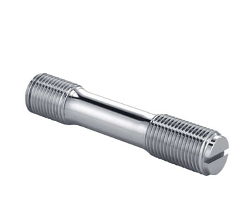
DIN 2510 Waisted Studs (Reduced Shank Studs): Manufacturer & Distributor
A reduced shank stud has a plain shank thinner than its thread. Tightened, the long slim waist stretches like a spring, and the joint keeps its clamping force when it settles, heats up or is loaded and unloaded.
Exotic Alloy manufactures waisted and reduced body studs in Mumbai, India, for turbine, valve, compressor and pressure-vessel builders and for power and process plants. We supply across India and export to Iraq, the Middle East, Central Asia and Africa.
Waisted or reduced body?
DIN 2510 waisted studs have a turned waist of about 0.9 times the thread root diameter. ASME B18.31.2 reduced body studs are only slightly thinner than the thread, about the pitch diameter. For a shank equal to the thread see double end studs; for flange sets see flange bolting.
- Standard
- DIN 2510-3 types L, K, KU, Z, ZU
- Sizes
- M12–M180 (type L to M52)
- Waist
- ≈ 0.86–0.92 × thread root
- Ends
- Spigot with two flats; KU, ZU second spigot
- Length
- Clamping length + 2c (DIN 2510-1)
- Inch
- ASME B18.31.2 reduced body
- Related
- Double end, flange bolting, nuts
Reduced Shank Stud Specification
The range we manufacture and supply.
DIN 2510 Types L, K, KU, Z & ZU
Same waist, different threads and ends.
| Type | Thread, M24 | Ends | Nuts (DIN 2510-1 examples) | Sizes |
|---|---|---|---|---|
| L | 32 mm | Spigot with flats | NF hexagon nuts | M12–M52 |
| K | 24 mm (≈ 1 d) | Spigot with flats | NF; TF with sleeves D | M12–M180 |
| KU | 24 mm | Flats + round spigot dp | AF cap nuts; BF with sleeves D | M12–M120 |
| Z | 42 mm | Spigot with flats | NF hexagon nuts | M12–M120 |
| ZU | 42 mm | Flats + round spigot dp | AF cap nuts | M12–M120 |
In DIN 2510-3 type K runs to M180, types KU, Z and ZU to M120 and type L to M52. From M64 the studs have an axial bore d4. The stud in our photo has a slot in one end instead of the spigot.
Waisted Stud Dimensions & Length Constants
| Size | Waist ds | Thread b type L / K / Z | Spigot d1 / flats s / z2 | Second spigot dp z3 KU / ZU | Bore d4 | Centre hole |
|---|---|---|---|---|---|---|
| M12 | 8.5 | 20 / 13 / 27 | 8 / 7 / 4 | 8 (11 / 7) | – | A1.6 |
| M16 | 12 | 23 / 16 / 31 | 12 / 10 / 5 | 12 (14 / 8) | – | A1.6 |
| M20 | 15 | 28 / 20 / 36 | 14 / 11 / 6 | 13 (16 / 9) | – | A1.6 |
| M24 | 18 | 32 / 24 / 42 | 14 / 11 / 6 | 16 (17 / 8) | – | A1.6 |
| M27 | 20.5 | 35 / 27 / 47 | 18 / 13 / 6 | 18 (19 / 10) | – | A1.6 |
| M30 | 23 | 39 / 30 / 50 | 18 / 13 / 6 | 21 (19 / 12) | – | A2.5 |
| M33 | 25.5 | 42 / 33 / 53 | 25 / 22 / 9 | 24 (21 / 14) | – | A2.5 |
| M36 | 27.5 | 45 / 36 / 57 | 25 / 22 / 9 | 26 (23 / 14) | – | A2.5 |
| M39 | 30.5 | 48 / 39 / 60 | 28 / 24 / 10 | 30 (23 / 14) | – | A2.5 |
| M42 | 32.5 | 52 / 42 / 64 | 28 / 24 / 10 | 32 (24 / 15) | – | A2.5 |
| M45 | 35.5 | 55 / 45 / 66 | 32 / 27 / 11 | 34 (25 / 15) | – | A2.5 |
| M48 | 37.5 | 58 / 48 / 70 | 32 / 27 / 11 | 37 (26 / 19) | – | A2.5 |
| M52 | 41 | 62 / 52 / 74 | 36 / 30 / 12 | 40 (26 / 18) | – | A2.5 |
| M56 | 44 | – / 56 / 79 | 40 / 32 / 13 | 45 (28 / 19) | – | A2.5 |
| M64 | 51 | – / 64 / 88 | 42 / 36 / 14 | 52 (28 / 20) | 18 | A4 |
| M72 × 6 | 58.5 | – / 72 / 95 | 50 / 41 / 15 | 56 (28 / 20) | 25 | A4 |
| M80 × 6 | 66 | – / 80 / 103 | 50 / 41 / 15 | 63 (28 / 19) | 25 | A4 |
| M90 × 6 | 75 | – / 90 / 112 | 50 / 41 / 15 | 74 (28 / 20) | 25 | A4 |
| M100 × 6 | 84 | – / 100 / 122 | 50 / 41 / 15 | 86 (28 / 19) | 25 | A4 |
| M110 × 6 | 92.5 | – / 110 / 132 | 50 / 41 / 15 | 97 (28 / 19) | 25 | A6.3 |
| (M120 × 6) | 102 | – / 120 / 142 | 50 / 41 / 15 | 105 (30 / 20) | 25 | A6.3 |
| M125 × 8 | 106 | – / 125 / – | 50 / 41 / 15 | – | 25 | A6.3 |
| M140 × 8 | 118 | – / 140 / – | 65 / 55 / 18 | – | 36 | A6.3 |
| (M150 × 8) | 127 | – / 150 / – | 65 / 55 / 18 | – | 36 | A6.3 |
| M160 × 8 | 136 | – / 160 / – | 65 / 55 / 18 | – | 36 | A6.3 |
| (M170 × 8) | 145 | – / 170 / – | 65 / 55 / 18 | – | 36 | A6.3 |
| M180 × 8 | 154 | – / 180 / – | 65 / 55 / 18 | – | 36 | A6.3 |
DIN 2510-3 (1971), mm. ds waist; b thread at both ends for types L, K and Z (KU as K, ZU as Z); spigot d1 with flats s, length z2; second spigot dp with length z3 on KU and ZU; axial bore d4 from M64; centre holes form A. Sizes in brackets to be avoided.
| Size | c1 | c2 | c3 min | c4 | c5 | c6 | c7 | c8 min |
|---|---|---|---|---|---|---|---|---|
| M12 | 14 | 12 | 16 | 30 | 18 | 28 | 16 | 17 |
| M16 | 18 | 16 | 20 | 35 | 21 | 33 | 19 | 21 |
| M20 | 22.5 | 20.5 | 24 | 41 | 25 | 39 | 23 | 25 |
| M24 | 27 | 24 | 29 | 46 | 29 | 44 | 27 | 30 |
| M27 | 30 | 27 | 32 | 51 | 32 | 49 | 30 | 33 |
| M30 | 33.5 | 30.5 | 36 | 56 | 36 | 54 | 34 | 36 |
| M33 | 36.5 | 33.5 | 39 | 61 | 39 | 59 | 37 | 39 |
| M36 | 40 | 37 | 43 | 65 | 42 | 63 | 40 | 43 |
| M39 | 43 | 40 | 46 | 67 | 45 | 65 | 43 | 45 |
| M42 | 46.5 | 43.5 | 49 | 72 | 48 | 70 | 46 | 49 |
| M45 | 49.5 | 46.5 | 52 | 75 | 51 | 73 | 49 | 51 |
| M48 | 53 | 49 | 56 | 82 | 56 | 80 | 54 | 55 |
| M52 | –* | 53 | 60 | 86 | 59 | 84 | 57 | 59 |
| M56 | 61.5 | 57.5 | 64 | 91 | 64 | 89 | 62 | 63 |
| M64 | 70 | 66 | 73 | 100 | 72 | 98 | 70 | 71 |
| M72 × 6 | 78 | 74 | 81 | 108 | 80 | 106 | 78 | 78 |
| M80 × 6 | 86 | 82 | 89 | 115 | 87 | 113 | 85 | 85 |
| M90 × 6 | 96 | 92 | 99 | 124 | 97 | 122 | 95 | 94 |
| M100 × 6 | 106 | 101 | 109 | 133 | 106 | 131 | 104 | 103 |
| M110 × 6 | 116 | 111 | 119 | 142 | 115 | 140 | 113 | 112 |
| (M120 × 6) | 126 | 121 | 129 | 153 | 124 | 151 | 122 | 121 |
DIN 2510-1, mm, for the stud length rules in section 06. *M52 c1 is misprinted in the copy we hold, so it is left out; ask us for M52 types L and K with NF nuts.
| Size | Reduced body ds1 min UNC / UNF / 8UN, in | Full body ds max | Metric size | ds1 min mm |
|---|---|---|---|---|
| 1/4 in | .213 / .223 / – | 0.2500 | M6 | 5.21 |
| 3/8 in | .329 / .343 / – | 0.3750 | M8 | 7.04 |
| 1/2 in | .444 / .462 / – | 0.5000 | M10 | 8.86 |
| 5/8 in | .559 / .583 / – | 0.6250 | M12 | 10.68 |
| 3/4 in | .677 / .703 / – | 0.7500 | M16 | 14.5 |
| 7/8 in | .795 / .822 / – | 0.8750 | M20 | 18.16 |
| 1 in | .910 / .938 / – | 1.0000 | M24 | 21.8 |
| 1-1/4 in | 1.148 / 1.188 / 1.160 | 1.2500 | M30 | 27.46 |
| 1-1/2 in | 1.381 / 1.438 / 1.409 | 1.5000 | M36 | 33.12 |
| 2 in | 1.843 / – / 1.909 | 2.0000 | M42 | 38.78 |
| 2-1/2 in | 2.324 / – / 2.408 | 2.5000 | M48 | 44.43 |
| 3 in | 2.824 / – / 2.908 | 3.0000 | M64 | 59.74 |
| 3-1/2 in | 3.323 / – / 3.407 | 3.5000 | M80 | 75.74 |
| 4 in | 3.823 / – / 3.907 | 4.0000 | M100 | 95.72 |
ASME B18.31.2 (inch) and B18.31.1M (metric) reduced body studs; ds1 minimum, which sits just below the basic pitch diameter. Inch reduced body maximum = full body minimum.
Why a Thin Shank Keeps the Preload
- Purpose: DIN 2510-1 uses waisted studs where preload and fatigue life must hold under changing mechanical and thermal loads.
- Spring effect: more stretch per kN, so a given settling or thermal mismatch costs less preload.
- Weakest part: the waist, at 67–81 % of the thread stress area, carries the highest stress.
- Thread: DIN 2510-2 gives the stud thread extra clearance.
| Size | Waist ds | Thread root d3 basic | ds / d3 | Waist area mm² | Waist / stress area As | Waist / full body area |
|---|---|---|---|---|---|---|
| M12 | 8.5 | 9.85 | 0.86 | 57 | 67 % | 50 % |
| M16 | 12 | 13.55 | 0.89 | 113 | 72 % | 56 % |
| M20 | 15 | 16.93 | 0.89 | 177 | 72 % | 56 % |
| M24 | 18 | 20.32 | 0.89 | 254 | 72 % | 56 % |
| M30 | 23 | 25.71 | 0.89 | 415 | 74 % | 59 % |
| M36 | 27.5 | 31.09 | 0.88 | 594 | 73 % | 58 % |
| M42 | 32.5 | 36.48 | 0.89 | 830 | 74 % | 60 % |
| M48 | 37.5 | 41.87 | 0.90 | 1104 | 75 % | 61 % |
| M56 | 44 | 49.25 | 0.89 | 1521 | 75 % | 62 % |
| M64 | 51 | 56.64 | 0.90 | 2043 | 76 % | 64 % |
| M80 × 6 | 66 | 72.64 | 0.91 | 3421 | 79 % | 68 % |
| M100 × 6 | 84 | 92.64 | 0.91 | 5542 | 79 % | 71 % |
| (M120 × 6) | 102 | 112.64 | 0.91 | 8171 | 80 % | 72 % |
| M160 × 8 | 136 | 150.19 | 0.91 | 14527 | 80 % | 72 % |
Our calculation from DIN 2510-3: d3 = d − 1.2269 P (ISO basic), As per ISO 898-1.
DIN 2510 Assemblies & the Stud Length Rule
| Stud type | Expansion sleeve | Nuts | Centring | Stud length l1 | Length steps |
|---|---|---|---|---|---|
| L | – | NF | by the studs | clamping length + 2 c1 | 1 mm |
| L | E | NF | by studs and sleeves | clamping length + 2 c1 | 1 mm |
| K | – | NF | by the nuts | clamping length + 2 c1 | 1 mm |
| K | D | TF | by nuts and sleeves | clamping length + 2 c2 | 1 mm |
| Z | – | NF | by the studs | clamping length + 2 c3 | 5 mm |
| Z | E | NF | by studs and sleeves | clamping length + 2 c3 | 5 mm |
| KU | – | AF (cap) | by the cap nuts | clamping length + c4 + c5 | 1 mm |
| KU | D | BF (cap) | by cap nuts and sleeves | clamping length + c6 + c7 | 1 mm |
| ZU | – | AF (cap) | by the studs | clamping length + c4 + c8 | 5 mm |
| ZU | E | AF (cap) | by studs and sleeves | clamping length + c4 + c8 | 5 mm |
DIN 2510-1 assembly examples; clamping length includes any expansion sleeves. NF and TF hexagon nuts, AF and BF cap nuts and the sleeves D and E belong to the DIN 2510 system.
Waisted Stud Length & Stretch Finder
DIN 2510 length for your joint, and what the waist does at your preload.
Stud & joint
Our calculation. Clamping length = everything clamped between the nuts, including expansion sleeves. Stud length l1 from DIN 2510-1: clamping length + the constants of the assembly, rounded up to 1 mm, or 5 mm for types Z and ZU. Rp0.2 = 0.2 % proof strength of your stud material at its working temperature; preload as a share of the waist yield force. Stretch = F · 100 / (E · A), E = 210 GPa, per 100 mm of shank.
Result
Waisted Stud Materials
| Material | Grades | Where |
|---|---|---|
| Heat-resistant Cr-Mo-V steel | 21CrMoV5-7 (EN 10269); ASTM A193 B16 | Turbine casings, hot flanges |
| Cr-Mo alloy steel | 42CrMo4 (EN 10269); ASTM A193 B7 | Valves, compressors, pressure equipment |
| Stainless steel | 304, 316 types; A193 B8, B8M | Corrosive service, as in the photo |
| Nickel alloys | Inconel 718, A-286, Nimonic 80A | Highest temperatures |
How Our Waisted Studs Are Made
Bar
Heat-treated alloy bar, certified by heat.
Turn
Centre holes, waist and transitions turned.
Polish
Waist and transitions finished smooth.
Thread
Threads rolled or cut to DIN 2510-2.
Spigot
Spigot and flats milled; bore from M64.
Inspect
Crack testing, marking and packing.
Where Our Reduced Shank Studs Are Used
Steam & gas turbines
Casing joints that heat up and cool down.
Valves
High-pressure, high-temperature bonnets.
Pressure vessels
Hot flanges and covers.
Power plant piping
Flanged joints in steam lines.
Compressors & engines
Joints under cyclic loads.
Chemical reactors
Covers with thermal cycling.
Waisted Stud Inspection & Certification
| Check | Method | Applied to |
|---|---|---|
| Waist diameter | Micrometer at several points | Every stud |
| Threads | Ring gauges to DIN 2510-2 | Every lot |
| Surface of waist | Visual and roughness | Every stud |
| Cracks | Magnetic particle or dye penetrant | As ordered |
| Mechanical | Tensile, impact, hardness | Every heat-treat lot |
| Material | PMI / chemical analysis | Alloys |
Every shipment includes
- EN 10204 3.1 certificate with heat number
- Dimensional report with waist diameters
- Identification on every stud
On request
- EN 10204 3.2 with third-party inspection
- Elevated-temperature tests
- Crack test reports